


EN 54-16 certified PA/VA System SERIES
5 6 , c h e m i n d e l a Fl a m b è re · 3 1 3 0 0 To u l o u s e · F R A N C E · T é l . 3 3 ( 0 ) 5 6 1 3 1 8 6 8 7
F a x 3 3 ( 0 ) 5 6 1 3 1 8 7 7 3 · c o m m e r c i a l @ m a j o r c o m . f r · w w w . m a j o r c o m . f r
User manual V1.1
5 6 , c h e m i n d e l a Fl a m b è re · 3 1 3 0 0 To u l o u s e · F R A N C E · T é l . 3 3 ( 0 ) 5 6 1 3 1 8 6 8 7
F a x 3 3 ( 0 ) 5 6 1 3 1 8 7 7 3 · c o m m e r c i a l @ m a j o r c o m . f r · w w w . m a j o r c o m . f r
Usermanual V1.1
9
8
SERIES EN 54-16 certified PA/VA System
Page
8
sur
51
Ϯ͘Ϯ
CONTROLS
Ϯ͘Ϯ͘ϭ
DIRECT ACCESS CONTROLS
These controls are located on the left side of the screen. They allow direct access to the notification
windows of the active states. They show extended information about operating status and available
options.
ĂͿ
EMG: “EMERGENCY”
It allows access to emergency status menu. When the equipment or system is in this state, you will
enter directly to the window with extended information about the state of emergency. To continue
operating the equipment, press the " BACK" button.
ďͿ
FLT: “FAULT”
It allows access to the window of extended information about the fault state. Faults are displayed
while the fault is not restarted, and up to 5 minutes after a reboot had occurred.
ĐͿ
DIS: “DISARMED”
Assesses the disarmed menu. If there is a disabled zone, it will go directly to the window with
extended information about the disable state.
ĚͿ
PA / BACK: “PA/BACK”
It allows access to the PA menu when the equipment is not in a state of emergency, or failure.
It also allows the go-back function for navigation through the menus. The button "PA" will change to
"BACK" button when the option is available again.
Ϯ͘Ϯ͘Ϯ
SCROLL BUTTONS
The scroll buttons are situated to the right side of the screen. They allow a scroll up / down within
the windows displayed on the screen. It includes the "OK" button for operations that require
confirmation.
Ϯ͘Ϯ͘ϯ
TEST
The "TEST" button is located under the direct access controls. It allows to check the correct
functioning of all indicators of the equipment. While the "TEST" button is being pressed it will turn on
simultaneously, all the indicators, and an audible warning will be emitted. The screen will go into the test
mode. Once the button is released, the test will end. During the testing process all manual controls will
be inactive. If they receive a signal from the CIE, for the activation of an emergency warning, the test will
end.
Ϯ͘Ϯ͘ϰ
RESET/ RST
The "RESET" button is located on the top right side of the screen. The "RESET" button resets the
operating condition of the equipment when it is in a state of emergency or fault.
NOTE: If pushed twice in an interval of time less than 10 seconds, it will perform a software reset of
the control module of EXEO and its extensions. This action stops the execution of events, stops the
microphones, playback of pre-recorded messages, etc.
Picture 2: Controls
Page
9
sur
51
Ϯ͘Ϯ͘ϱ
ACK
The button "ACK" is situated under the button "RESET" on the right side of the screen. I allow the
confirmation that the emergency mode or fault status indication has been acknowledged. By pressing it,
the emergency or fault audible beep will be muted.
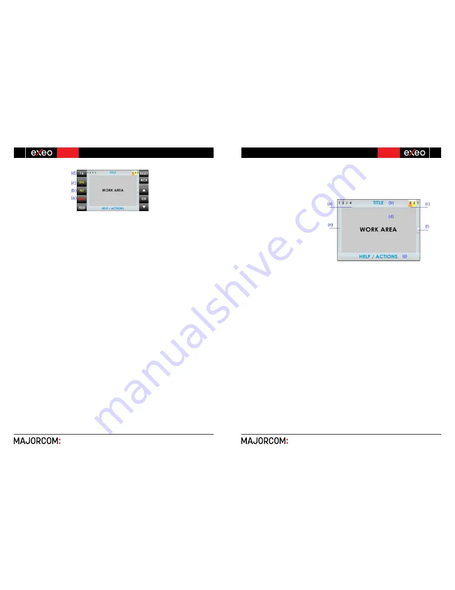
Ϯ͘Ϯ͘ϲ
CONTROL WINDOW
The
following
describes
the
information that, continuously, can be
viewed in the control window.
ĂͿ
NAVIGATION LEVEL
In the upper right side there is the
menu level indicator in which the user is
located. As we examine the menu, it
displays a higher level.
ďͿ
TITLE
On the top of the window, it indicates
the title of the section in which the user is
operating.
ĐͿ
ACCESS LEVEL
Located in the upper right corner of the screen, it indicates the current access level (see 2.3).
ĚͿ
WORKING AREA
The central area of the screen will show the information or controls that are available to the user.
ĞͿ
LEFT BAR
Indicated by different colors, and along with the title, the menu in which the user is working. For
emergency is red and for fault or disarmed zones is yellow.
ĨͿ
SCROLL BAR
At some windows, this item may appear. It indicates that there are more objects to be displayed in
the same window upwards or downwards. To access them, use the scroll buttons (see 2.2.2.).
The scroll bar can have three positions, top, middle or bottom, indicating, beginning, middle and end
area respectively.
ŐͿ
HELP / ACTION
In the lower area of each window there is a help text indicating the next step to be performed by the
user.
Picture 3: Control window


