5
M1
M2
BK/GR
BK/GR
WH
WH
YE
YE
OR
OR
ABL
ZUL
ZUL
ABL
r.F.
T-LET
T-FOL
T-ZUL
ZP1
BN
BU
GNYE
GNYE
BU
BN
WH
BN
GN
YE
PTC- Heizregister
Bypassmotor
BN
BU
GNYE
L
N
PE
S1
GNYE
BU
BN
GNYE
BU
BN
LD3
LD2
LD1
S1+
S2-
B1
W2
W2'
W1
W2
M3
1
2
3
4
5
6
W4
W6
W7
A
A1
W8
W9
MAICO
Steuerung KWL
1 2 3 4 5
X7
Bypass
T1
T2
T3
T4
X8
Fühler
X9
Abluft
Zuluft
X10
Digita
lR
S485
X11
X12
Sensoren
RLS
X13
X1
PE
NL
Netz
PE
NL
Option
X3
12
X4
PE
NL
PE
NL
Zuluft
Abluft
X5
PE
NL
Heizregister
X6
12
Kontakt
Ethernet
USB
2
1
X2
NC
NC
3.
3S
DS
C
AB
12V
LD2
LD1
S1+
S2-
LD3
24V
24V
4
3
2
1
S-ABL
W3
BK
WHBN GN YE GR
XO1
1 2 3 4
BT1
A2
LD3
LD2
LD1
S1+
S2-
B2-B5
W2
WH
BN
GN
YE
GR
W5
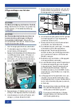
8. Wire connection cable for bypass motor
W7 onto main circuit board (terminal X7)
according to wiring diagram.
9. Slide electronic slide-in module into elec-
tronic compartment and screw down.
10. Fit front cover(s)
Installation instructions
for ventilation unit.
11.
Affix the retrofit sticker provided on the
ventilation unit such that it is clearly visi-
ble. Enter installed function and date on
WS-BP.
12. Switch on the mains fuse, switch on the
ventilation unit with the main switch.
13. On an operating unit, activate the bypass
by selecting
yes
under
Settings / Basic
settings/Bypass
. This setting can be
undertaken using commissioning software,
WebTool (installer level), comfort control
unit (installer level) or web server.
14.
Use main switch to briefly switch ventila
-
tion unit off and on again. The ventilation
unit now performs a reference run and
closes the bypass (vertical position).
i
The bypass is automatically blocked if
the
Winter
season is selected or at an
air inlet temperature < 5 °C
.
i
For more information
Operating
instructions and commissioning and
maintenance instructions.
5 Replacing bypass shutter
If only the bypass shutter is being replaced,
proceed as follows. If the motor is defective,
proceed as described in Chapter 4.
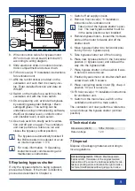
1. Switch off all supply circuits.
2. Remove front cover(s)
Installation
instructions for ventilation unit.
i
Take note of the bypass shutter’s posi-
tion. The new bypass shutter must be
in the same position when installed.
3. Remove bypass motor – loosen the 3 screws
and pull the motor forwards and off the
shutter shaft.
4. Move bypass shutter into horizontal posi-
tion by hand (= bypass open).
5. Take bypass shutter out of the housing.
6. Place new bypass shutter in the horizontal
position (= bypass open) and slide all the
way into the bypass shaft.
7. Place bypass shutter in the position it was
in before it was removed.
8. Position bypass motor on shutter shaft and
screw down with 3 screws.
9.
Place connecting cable in slot (fig. chap. 4
position “III”) so it is secure.
10. Fit front cover(s)
Installation instructions
for ventilation unit.
11. Switch on the mains fuse, switch on the
ventilation unit with the main switch.
The ventilation unit now performs a reference
run and closes the bypass shutter (vertical
position).
6 Technical data
Dimensions (WxD)
505 x 193 mm
Rated voltage
12 V
7 Disposal
Dispose of packaging material according to
local regulations.
Acknowledgements:
© Maico Elektroapparate-
Fabrik GmbH. Translation of the original German
instructions. We cannot be held responsible for mis-
takes or printing errors and retain the right to make
technical modifications without giving prior notice.
bypass motor


