Magtrol HD-106-1 Скачать руководство пользователя страница 18

13

4.  Operating Principles

4.1 SPEED

The dynamometer is shipped with an internal speed pickup and two cords: one terminating with a 
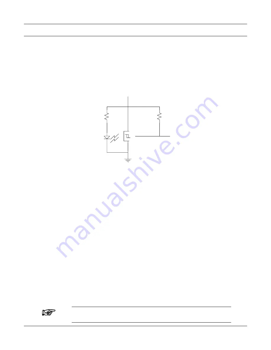
2-pin plug for the brake power, the other is a 14-pin plug servicing an optical encoder.  This encoder 
consists of an infrared transmitter/receiver pair. On the end of the dynamometer shaft, positioned 
between the LED and detector, is an optical disc with opaque and clear segments.  Rotation of the 
disc results in the detector generating a frequency of 60 pulses per shaft revolution.

R1

470

U1

4

OPB963

2

3

Fo

R2

200

5V (Pin 7)

5

(Pin 8)

(Pin 10)

1

Figure 4–1  Optical Encoder Circuit

4.2 TORQUE

Torsional force, acting upon the hysteresis brake, is produced by the test motor, and applied to the 
brake’s rotor-shaft assembly.  Whatever torque exists on the rotor-shaft, must be reacted upon equally 
by the suspended brake-dial-weight assembly.  

Since the brake assembly is imbalanced by the suspended weight attached to it, torsional force will 
lift the weight.  The graduated dial provides a readout value equal to this torque.   Once the weights 
are calibrated to match the dial graduations, the system accuracy becomes permanently fixed.

When torque is defined by a point on the radius of a weight, lifted in a circular motion, the scale 
derivation is inherently a cosine function - thus, the nonlinear scale graduations.

4.2.1 

t

orque

 s

taBility

A major advantage in using a hysteresis brake as a loading means, is the ability to produce torque 
essentially independent of speed.  This permits very low speed and locked rotor torque testing. 

Three factors have a minor secondary influence on hysteresis brake torque.   They are:

•  Hysteresis brake control current (

see Section 1.2.1

)

•  Eddy current (

see Section 3.9

)

•  Temperature rise (

see Section 3.10

)


Note: 

Torque changes as a result of these influences are always part of the 
actual torque measured—as applied to a test motor—and not errors.

Содержание HD-106-1

Страница 1: ...HD 1 HD 2 Series Dial Weight Dynamometers User s Manual...

Страница 2: ...any part of the contents of this manual without the express permission of Magtrol is strictly prohibited Purchase Record Please record all model numbers and serial numbers of your Magtrol equipment a...

Страница 3: ...anges updates that have been made since this edition REVISION DATE 1st Edition Revision B August 2008 TABLE OF REVISIONS Revisions To This Manual Date Edition Change Section s 12 18 08 1st Edition Rev...

Страница 4: ...TEM CONFIGURATION 2 2 3 1 SPEED READOUTS 2 2 3 2 POWER SUPPLIES 2 2 3 3 CONNECTIONS 3 2 4 INITIAL CHECKOUT 3 3 TESTING CONSIDERATIONS 4 3 1 SAFETY 4 3 2 ACCURACY 4 3 2 1 TORQUE SCALE GRADUATIONS 5 3 3...

Страница 5: ...gure 3 3 HD 400 1 2 Power Absorption Curve 7 Figure 3 4 HD 500 1 Power Absorption Curve 7 Figure 3 5 HD 600 1 Power Absorption Curve 8 Figure 3 6 HD 700 1 Power Absorption Curve 8 Figure 3 7 HD 705 1...

Страница 6: ...L SPECIFICATIONS Model Full Scale Torque Maximum Speed Power Ratings Range One Range Two Range Three 5 Minutes Continuous oz in accuracy oz in accuracy oz in accuracy rpm W W HD 106 1 0 5 3 5 1 2 2 1...

Страница 7: ...more accurate to level the dynamometer by observing the torque dial for a ZERO reading It works best to use the most sensitive torque scale by removing one or both of the counter weights 0 Figure 2 1...

Страница 8: ...eadout device if applicable and the torque controller 3 Rotate the dynamometer shaft manually while simultaneously adjusting the TORQUE CONTROL clockwise very slowly 4 Stop when you begin to feel resi...

Страница 9: ...y computer in use or operating personnel with dangerous and costly consequences Always connect the motor frame to a high current capacity water pipe earth ground Be sure the motor control circuit brea...

Страница 10: ...the rotating assembly to contact the stationary members that surround it Once this happens metal transfer and ultimately seizing of the brake assembly may occur Excessive power over extended periods o...

Страница 11: ...used in the following specifications Figure 3 1 Dynamometer Side View HD 106 1 Shaft Diameter 0 1245 in 0 1250 in 3 163 mm 3 175 mm Shaft Height 3 50 in 88 9 mm Torque Ranges 0 5 oz in 1 0 oz in 2 0 o...

Страница 12: ...16 oz in 32 oz in Input Inertia 1 55 10 5 lb ft s Maximum Speed 25 000 rpm Maximum Input Power 190 W Figure 3 3 HD 400 1 2 Power Absorption Curve HD 500 1 Shaft Diameter 0 3745 in 0 3750 in 9 512 mm...

Страница 13: ...nput Inertia 2 34 10 5 lb ft s Maximum Speed 20 000 rpm Maximum Input Power 550 W Figure 3 5 HD 600 1 Power Absorption Curve HD 700 1 Shaft Diameter 0 4995 in 0 5000 in 12 687 mm 12 700 mm Shaft Heigh...

Страница 14: ...re the test motor in the fixture to prevent torsional movement and bolt the fixture to the dynamometer base plate Give consideration to the interaction of materials between the motor and test fixture...

Страница 15: ...oss due to windage ranges between 0 025 and 0 20 of full scale at maximum rated rpm The larger percentage applies toward the smallest capacity dynamometer HD 106 Because windage is proportional to the...

Страница 16: ...GGING Pole Case Rotor Poles Rotor Assembly S S S N N N Figure 3 9 Hysteresis Brake Cross Section This cross section shows by one tooth the magnetic relationship of the hysteresis brake elements If the...

Страница 17: ...r dynamometers On the smaller dynamometer sizes 2 to 4 1000 rpm is typical 3 10 TEMPERATURE RISE Temperature rise has a more complex effect on hysteresis brake load torque and is difficult to quantify...

Страница 18: ...al weight assembly Since the brake assembly is imbalanced by the suspended weight attached to it torsional force will lift the weight The graduated dial provides a readout value equal to this torque O...

Страница 19: ...ing diagram Lock the beam with the locking screw against the flat on the shaft Do not hang the weight until instructed to do so in step 4 With the Base Plate and the Beam level Dial Reading D x W LEVE...

Страница 20: ...lle Parkway Buffalo New York 14224 USA Phone 1 716 668 5555 Fax 1 716 668 8705 E mail magtrol magtrol com MAGTROL SA Route de Montena 77 1728 Rossens Fribourg Switzerland Phone 41 0 26 407 3000 Fax 41...

Отзывы: