


11
Magtrol Dial Weight Dynamometers
User’s Manual
3.7
VIBRATION
All rotating dynamometer assemblies are precision balanced, however, the dynamometer shaft is
cantilevered. This may cause vulnerability to radial forces.
At high speeds, some vibration and noise are inevitable but not necessarily harmful. However,
excessive resonant vibrations, caused by bent shafts, poor alignment and out of balance couplings
will produce excessive data errors and are a safety hazard.
WARNING! S H A F T C O U P L I N G S O P E R AT I N G AT S P E E D S
ABOVE THEIR DESIGN LIMITS ARE EXTREMELY
HAZARDOUS. MANY COUPLINGS CONTAIN SOMEWHAT
LOOSELY SUPPORTED FLEXURE ELEMENTS. WHEN
OVERDRIVEN, EXCESSIVE CENTRIFUGAL FORCE
MAY DISPLACE THEM OUT OF AXIAL ALIGNMENT.
AS THIS HAPPENS, THEY IMMEDIATELY BEGIN TO
ABSORB ENERGY RESULTING IN SEVERE VIBRATION
AND DESTRUCTION OF THE COUPLING.
3.8
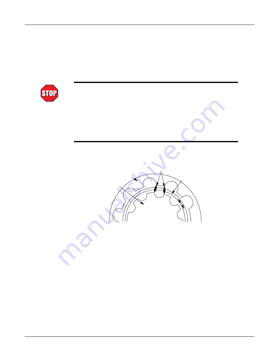
COGGING
Pole
Case
Rotor Poles
Rotor
Assembly
S
S
S
N
N
N
Figure 3–9 Hysteresis Brake Cross-Section
This cross-section shows (by one tooth) the magnetic relationship of the hysteresis brake elements.
If the dynamometer shaft is at rest with torque applied, and if the torque control is then reduced to
zero, a magnetic salient pole will be temporarily imposed on the rotor of the brake.
If the shaft is then rotated slowly, the magnetic poles on the rotor will attempt to align with the adjacent
case-pole tooth form. This is often referred to as “cogging”. The action is sinusoidal—first it tries to
resist rotation and then, as the rotor passes through the tooth form, it subsequently supports rotation.
At a few hundred rpm, these forces integrate resulting in an effective torque of nearly zero.
To avoid magnetic cogging, before the shaft comes to rest, reduce the torque control to zero.
To remove cogging, once established, reapply current on the dynamometer. Then, decrease the
current to zero while simultaneously rotating the dynamometer shaft.