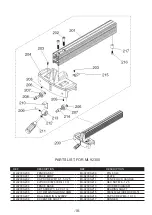
background image

-4-

2.  Grounded, cord-connected tools intended for use on a supply circuit having a nominal rating 

less than 150 volts:

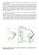
This tool is intended for use on a circuit that has an outlet that looks like the one illustrated in 

Sketch A in Figure 1. The tool has a grounding plug that looks like the plug illustrated in Sketch 

A in Figure 1. A temporary adapter, which looks like the adapter illustrated in Sketches B and 

C, may be used to connect this plug to a 2-pole receptacle as shown in Sketch B if a properly 

grounded outlet is not available. The temporary adapter should be used only until a properly 

grounded outlet can be installed by a qualified electrician. The green-colored rigid ear, lug, 

and the like, extending from the adapter must be connected to a permanent ground such as a 

properly grounded outlet box.

3.  Grounded, cord-connected tools intended for use on a supply circuit having a nominal rating 

between 150-250 volts, inclusive:

This tool is intended for use on a circuit that has an outlet that looks like the one illustrated in 

Sketch D in Figure 1. The tool has a grounding plug that looks like the plug illustrated in Sketch 

D in Figure 1. Make sure the tool is connected to an outlet having the same configuration as the 

plug. No adapter is available or should be used with this tool. If the tool must be reconnected for 

use on a different type of electric circuit, the reconnection should be made by qualified service 

personnel; and after reconnection, the tool should comply with all local codes and ordinances.


Note : In Canada, the use of a temporary adaptor is not 

permitted by the Canadian Electrical Code. 

GROUNDING 
PIN 

COVER OF GROUNDED 
OUTLET BOX 

METAL SCREW 

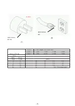
(A) 

(B) 

FIGURE 1 

Grounding methods 

Note : In Canada, the use of a temporary adaptor is not permitted by the 

Canadian Electrical Code.

Содержание MI-92300

Страница 1: ...MODEL NO MI 92300 OPERATING MANUAL START STOP ON OFF...

Страница 2: ...job better and safer at the rate for which it was not designed 10 USE RIGHT TOOL Don t force tool or attachment to do a job for which it was not designed 11 USE PROPER EXTENSION CORD Make sure your e...

Страница 3: ...only 23 NEVER LEAVE TOOL RUNNING UNATTENDED TURN POWER OFF Don t leave tool until it comes to a complete stop 24 MAME SURE TOOL IS DISCONNECTED from power supply while motor is being mounted connecte...

Страница 4: ...location that is inaccessible to children and others not qualified to use the tool GROUNDING INSTRUCTIONS 1 All grounded cord connected tools In the event of a malfunction or breakdown grounding prov...

Страница 5: ...outlet box 3 Grounded cord connected tools intended for use on a supply circuit having a nominal rating between 150 250 volts inclusive This tool is intended for use on a circuit that has an outlet th...

Страница 6: ...ANS C GROUNDING PIN D Ampere Rating Volta Total length of cord in feet 120V 25ft 50ft 100ft 150ft 240V 50ft 100ft 200ft 300ft Not More More Than Than AWG 0 6 18 16 16 14 6 10 18 16 14 12 10 12 16 16 1...

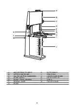
Страница 7: ...QUICK RELEASE HANDLE H MITER GUAGE B UPPER DOOR KNOBE I FENCE RAIL C GUARD CONTROL HANDWHEEL J LOWER DOOR KNOBE D BLADE GUARD K ON OFF SWITCH E BLADE THRUST BEARING L FENCE F BEARING GUIDE M TOOL STO...

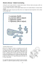
Страница 8: ...lade support Whenever changing a blade or adjusting tension and tracking the upper and lower blade support bearings and guide blocks must be re adjusted Always adjust the assemblies away from the blad...

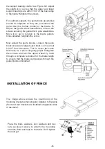
Страница 9: ...w Now adjust the guide blocks Loosen the guide block screws and adjust each block so it is about 0 004 from the blade This is about the same thickness as a piece of typing paper Retighten the screws a...

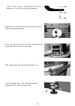
Страница 10: ...x 5 8 lock knob A and a square nut B on both rear mounting brackets Insert the square nut A of the first front mounting bracket into the T slot of the front rail B Then slide the rail onto the second...

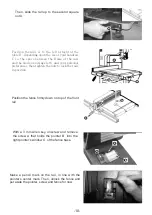
Страница 11: ...e left and your personal preferences then tighten the nuts to lock the rails in position Position the fence firmly down on top of the front rail With a 3 mm Allen key unscrew and remove the screw A th...

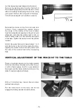
Страница 12: ...hat its center mark is in line with the zero point of the tape Tighten the screw to lock the pointer in place Unlock the guide fence and repeat steps 1 to 5 with the fence to the left of the blade thi...

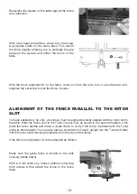
Страница 13: ...satisfactory rip cuts your fence must be aligned perfectly parallel with the miter slot in the table Slide the fence over to the T slot on your saw as shown in the second diagram Lock down the fence h...

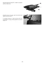
Страница 14: ...he fence B so that it is parallel with the miter slot C Hold the fence in place with one hand and tighten the first screw C If needed adjust a little further with the remaining bit of play then tighte...

Страница 15: ...14...

Страница 16: ...92300 59 4 3 CIRCUIT TERMINAL BLOCK MI 92300 21 LOWER WHEEL SHAFT MI 92300 60 FLAT WASHER 3 8 MI 92300 22 HEX NUT 3 8 1 6 MI 92300 61 SPECIAL SCREW 3 8 1 6 X 1 1 4 MI 92300 23 BALL BEARING 6204ZZ MI 9...

Страница 17: ......

Страница 18: ...N MI 92300 117 COMPRESSION SPRING MI 92300 149 HEX BOLT 5 16 18 X 3 4 MI 92300 119 GUIDE BAR KNOB 5 16 18 X 2 MI 92300 150 HEX BOLT 3 8 1 6 X 2 MI 92300 120 GEAR MI 92300 151 FLAT WASHER 3 8 MI 92300...

Страница 19: ...1 FENCE LOCK HANDLE MI 92300 203 BUTTON HD CAP SCR M6 1 X 10 MI 92300 212 HEX NUT M8 1 25 MI 92300 204 FENCE BASE MI 92300 213 LOCK MECHANISM MI 92300 205 SET SCREW 1 4 20 X 1 4 MI 92300 214 BEARING S...

Страница 20: ...FAULT DISPLAY...
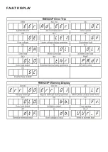
Страница 21: ...r is shutdown Output terminals U V W is short circuited overload acceleration time too small start at free running or mismatched characteristics of motor Over voltage O E Due to the higher regenerativ...

Страница 22: ...heck keypad and inverter connections S C Break of fuse inside the inverter Break of IGBT module Change inverter PAdF KP 202C is removed in running Resume KP 202C Ad_Err AD converter fault Change inver...

Отзывы: