background image

© 

2010 Magnum Energy, Inc

Page 47

Appendix C - Warranty & Service

Limited Warranty

Magnum Energy, Inc., warrants the RD-E Series inverter/charger to be free from defects in material 

and workmanship that result in product failure during normal usage, according to the following 

terms and conditions:
1.  The limited warranty for the product extends for 24 months beginning from the product’s 

original date of purchase.

2.  The limited warranty extends to the original purchaser of the product and is not assignable or 

transferable to any subsequent purchaser.

3.  During the limited warranty period, Magnum Energy will repair, or replace at Magnum Energy’s 

option, any defective parts, or any parts that will not properly operate for their intended use 

with factory new or remanufactured replacement items if such repair or replacement is needed 

because of product malfunction or failure during normal usage. The limited warranty does not 

cover defects in appearance, cosmetic, decorative or structural parts or any non-operative parts. 

Magnum Energy’s limit of liability under the limited warranty shall be the actual cash value of 

the product at the time the original purchaser returns the product for repair, determined by 

the price paid by the original purchaser. Magnum Energy shall not be liable for any other losses 

or damages.

4.  Upon request from Magnum Energy, the original purchaser must prove the product’s original 

date of purchase by a dated bill of sale, itemized receipt.

5.  The original purchaser shall return the product prepaid to Magnum Energy in Everett, WA. After 

the completion of service under this limited warranty, Magnum Energy will return the product 

prepaid to the original purchaser via a Magnum-selected non-expedited surface freight within 

the contiguous United States and Canada; this excludes Alaska and Hawaii.

6.  This limited warranty is voided if:

the product has been modi

fi

 ed without authorization

the serial number has been altered or removed
the product has been damaged from abuse, neglect, accident, high voltage or corrosion
the product was not installed and operated according to the owner's manual

How to Receive Repair Service

If your product requires warranty service or repair, contact either:
1.  An Authorized Service Center, which are listed on the Magnum Energy website at 

www.magnumenergy.com/servicecenters.htm

; or

2.  Magnum Energy, Inc. at:

Telephone: 425-353-8833

Fax: 425-353-8390

Email: [email protected]


If returning the product directly to Magnum Energy for repair, you must:

return the unit in the original, or equivalent, shipping container
receive a Return Materials Authorization (RMA) number from the factory prior to the 

return of the product to Magnum Energy for repair
place RMA numbers clearly on the shipping container or on the packing slip

When sending your Product for service, please ensure it is properly packaged. Damage due to 

inadequate packaging is not covered under warranty. We recommend sending the Product by 

traceable or insured service.

BEFORE RETURNING ANY UNIT TO MAGNUM ENERGY INC.,

A RETURN MATERIAL AUTHORIZATION (RMA) NUMBER IS REQUIRED


Содержание RD-E Series

Страница 1: ...RD E Series Modified Sine Wave Inverters Chargers Owner s Manual ...

Страница 2: ...ure of the RD E Series Inverter Charger can reasonably be expected to cause the failure of that life support device or system or to affect the safety or effectiveness of that device or system If the RD E Series Inverter Charger fails it is reasonable to assume that the health of the user or other persons may be endangered Copyright Notice Copyright 2004 2010 by Magnum Energy Inc All rights reserve...

Страница 3: ...oduct This unit is provided with integral protection against overloads The input and output AC and DC circuits are isolated from the inverter chassis The inverter system grounding is the responsibility of the installer in accordance with the NEC CEC and local codes Both AC and DC overcurrent protection must be provided as part of the installation Use Class 1 wiring methods for field wiring connect...

Страница 4: ...lways install batteries in a stable environment Install batteries in a well ventilated area Batteries can produce explosive gases For compartment or enclosure installations always vent batteries to the outside Provide at least one inch 2 5 cm of air space between batteries to provide optimum cooling Never smoke in the vicinity of batteries To prevent a spark at the battery and reduce the chance of...

Страница 5: ...attery Charging 31 3 4 Transfer Time 33 3 5 Battery Temperature Sensor Operation 33 3 6 Protection Circuitry Operation 34 3 7 Inverter Startup 35 3 8 Factory Default Values 36 4 0 Maintenance and Troubleshooting 37 4 1 Recommended Inverter and Battery Care 37 4 2 Troubleshooting 38 4 3 Resetting the Inverter 39 Appendix A Specifications and Optional Equipment 40 A 1 Inverter Charger Specifications...

Страница 6: ...ctions to DC Ground Rod Method 2 26 Figure 2 15 Single Connection to DC Ground Rod Method 3 26 Figure 2 16 Warning Label 28 Figure 2 17 AC Voltage Checks 29 Figure 3 1 Power Flow Inverter Mode 30 Figure 3 2 Power Flow Standby Mode 31 Figure 3 3 Automatic 4 Stage Charging Graph 32 Figure 3 4 BTS Temperature to Charge Voltage Change 33 Figure 3 5 Power Switch and Status Indicator 35 Figure 4 1 Perfo...

Страница 7: ...put Large AC access and terminal block wire size 10 to 6 AWG 5 3 to 13 3 mm2 CU DC terminal covers with 360 degree connection Field serviceable for qualified personnel tested repair kits available Automatic battery temperature compensation using battery temperature sensor for optimum charging even during extreme temperature changes Overcurrent over temperature and high low battery voltage protecti...

Страница 8: ...te Connection Port blue label a RJ11 port that allows the optional remote controls ME RC50 or ME ARC50 to be connected 6 BTS Connection Port yellow label RJ11 port that accepts the remote Battery Temperature Sensor BTS accessory 7 DC Equipment Ground Terminal this connection is used to tie the exposed chassis of the inverter to the DC grounding system This terminal accepts CU AL conductors from 14...

Страница 9: ...G LED STACK ACCESSORIES PORT RED LABEL RJ11 CONNECTION NETWORK PORT GREEN LABEL RJ11 CONNECTION REMOTE PORT BLUE LABEL RJ11 CONNECTION BATTERY TEMPERATURE SENSOR PORT YELLOW LABEL RJ11 CONNECTION INTAKE AIR VENTS AND ON RIGHT SIDE AC INPUT OUTPUT CONNECTIONS DC EQUIPMENT GROUND TERMINAL POSITIVE DC TERMINAL UNDER COVER NEGATIVE DC TERMINAL UNDER COVER MOUNTING FLANGE 6 5 4 3 2 1 11 10 12 7 8 9 ...

Страница 10: ...al block This terminal block is used to hardwire all inverter AC input and output wiring connections Remove the two screws to access the AC wiring terminal block 16 Input Circuit Breaker this circuit breaker protects the unit s internal charger wiring and pass thru relay while in Standby mode This circuit breaker will pop out when it opens Press in to reset This input circuit breaker is not branch...

Страница 11: ...prevent lost computer data or to maintain ligts and keep food fresh in the refrigerator freezer In some areas where utility power is not available the inverter can be used in a standalone renewable power system The inverter enables AC electrical appliances to be run from the storage battery bank When the battery bank becomes discharged either renewable DC sources solar wind or hydropower can be us...

Страница 12: ...lly located on its chassis near the AC power cord Even though it is difficult to calculate exactly how long an inverter will run a particular appliance the best advice is trial and error Your RD E Series inverter has a built in safeguard that automatically protects your batteries from over discharge Info For optimum performance a minimum battery bank of 200 AH is recommended for moderate loads 100...

Страница 13: ...erter charger The more thorough you plan in the beginning the better your inverter needs will be met 2 1 1 Unpacking and Inspection Carefully remove the RD E Series inverter charger from its shipping container and inspect all contents Verify the following items are included The RD E inverter charger Red and black DC terminal covers with Phillips screws AC access cover with two Phillips screws Two ...

Страница 14: ...K B attery M onitor with shunt M agnum A ccessory D C Shunt A C Transfer Switch Generator Power 230 VA C Output U tility Power 230 VA C Output F lu x C a p a c it o r G e n e r a t o r O N O F F O N O FF O N O F F O N O FF O N O F F O N O FF ON OFF O N O FF O N O FF O N O FF O N O F F O N O F F O N O FF B TS O N O FF O N O FF 30 A 3 0A M E SB C Sm art B attery C om biner M agnum A ccessory M E A G...

Страница 15: ...t air through the exhaust vents see Figure 1 3 Item 13 Allow at the minimum an airspace clearance of 6 15 2 cm at the intake and exhaust vents and 3 7 6 cm everywhere else to provide adequate ventilation If installed in an enclosure a fresh air intake opening must be provided directly to the front side intake vents of the inverter and an exhaust opening on the back side exhaust vents of the invert...

Страница 16: ...ith DC terminals toward the bottom MP HOOD inverter hood installed on the top and either the ME CB Conduit Box MPX CB Conduit Box or the MMP Series single inverter enclosure installed on the inverter s bottom Info The ME CB and MPX CB conduit boxes prevent material from falling out the bottom in the event of an internal fire The MP HOOD inverter hood helps prevent items from falling inside causing...

Страница 17: ... Side Reference 12 5 8 32 1 cm 12 30 5 cm 4 7 8 12 4 cm 2 5 1 cm 4 7 8 12 4 cm Keyhole slots x4 and mounting holes x4 accept up to 9 32 7 mm screw bolt 13 3 4 34 9 cm 8 20 3 cm 6 5 8 16 8 cm BOTTOM SIDE RIGHT SIDE BACK SIDE RIGHT SIDE LEFT SIDE TOP SIDE LEFT SIDE TOP SIDE FRONT SIDE ...

Страница 18: ...ng the ME CB conduit box and the AC wires are individual conductors i e not jacketed the strain reliefs can be removed and replaced with 3 4 grommets 2 3 2 Wiring Requirements All conductors that are at risk for physical damage must be protected by tape or placed in a raceway Always check for existing electrical plumbing or other areas of potential damage prior to making cuts in structural surface...

Страница 19: ...cts of inductance which improves the inverter waveform and reduces the wear of the inverter s filter capacitors Use crimped and sealed copper ring terminal lugs to connect the DC wires to the inverter s DC terminals We use 5 16 terminal lugs in U S determine the European equivalent The battery bank voltage must match the DC voltage required by the inverter i e 24 volt battery bank for a 24 volt in...

Страница 20: ...B attery Tem p Sensor C able Inverter s D C N egative C onnection Inverter s D C Positive C onnection Inverter s Equipm ent Ground Wire B TS B TS Battery Bank B attery B ank s Equipm ent Ground Wire B attery B ank s N egative C able B attery B ank s Positive C able MMP enclosure for single inverter installations includes D C disconnect breaker D C shunt for battery m onitor and inverter D C busbar...

Страница 21: ... maximum current carrying capability thereby preventing a fire The NEC requires both overcurrent protection and a disconnect switch If a circuit breaker is used as the overcurrent protection device it can also be used as the required DC disconnect If a fuse is used as an overcurrent device a Class T type or equivalent is recommended This fuse type is rated for DC operation can handle the high shor...

Страница 22: ...stance connection which could lead to poor inverter charger performance and may melt the cable and terminal connections Follow the examples in Figures 2 5 and 2 6 to connect the DC cables and stack the hardware correctly Tighten the terminal connections from 10 to 12 ft lbf 13 6 to 16 3 N m CAUTION The DC terminal and Kep nuts are made of stainless steel which has a high likelihood of seizure To h...

Страница 23: ...good air flow DO NOT mount the batteries directly under the inverter CAUTION Install batteries in a well ventilated area Batteries can produce explosive gases For compartment enclosure installations always vent batteries to the outside Info To ensure the best performance from your inverter system batteries should be of the same size type rating and age Do not use old or untested batteries 2 4 5 Ba...

Страница 24: ...breaker or fuse assembly as near as practical to the batteries and leave open i e no power to inverter WARNING DO NOT close the DC circuit breaker or connect the fuse to connect battery power to the inverter at this time This will occur in the Functional Test after the installation is complete CAUTION If connecting live battery cables to the inverter DC terminals a brief spark or arc may occur thi...

Страница 25: ...e sizes they are required to be protected from short circuits and overloads by an overcurrent protection device and have a means to disconnect the AC circuits The RD E Series allows the AC input and output wiring to be permanently wired The inverter s input is wired to the service distribution panel main panel The inverter s output is then wired to a dedicated panel sub panel The inverter uses the...

Страница 26: ...llation Figure 2 8 RD E Series Inverter Charger AC Wiring Figure 2 9 RD E Series Inverter Charger AC Wiring Access Cover AC Input Circuit Breaker CB3 AC Input Output Strain Relief Clamp AC Input Output Strain Relief Clamp AC Access Cover ...

Страница 27: ... maximum tightening torque is 16 in lbf 1 8 N m Info For alternative energy installations and to comply with standard safety requirements the four pole AC terminal is provided with a stainless steel wire protector to prevent wire damage from the set screw Info The inverter s NEUT IN and NEUT OUT terminals are connected together internally The AC ground terminal can accept one 14 to 6 AWG 2 1 to 13...

Страница 28: ...he LIVE OUT brown wire from the HOT OUT terminal to the sub panel main breaker Tighten the HOT OUT terminal to 16 in lbf 1 8 N m 3 Connect the NEUTRAL OUT blue from the NEUT OUT terminal to the sub panel s neutral busbar Tighten the NEUT OUT terminal to 16 in lbf 1 8 N m Wiring the Inverter AC Ground 1 Combine the ground green w yellow stripe wire from the main panel s ground busbar and the ground...

Страница 29: ... F F O N O FF O N O FF O N O F F O N O F F O N O FF O N O FF O N O F F O N O FF O N O F F Maximum 30 amp breaker single pole required to inverter AC input O N O F F O N O FF ON OFF A C H O T O U T to S ub P a nel A C N E U T O U T t o Sub Pa ne l AC G RO UNDS to from both panels A C N EU T IN f rom M ain P ane l A C H O T IN f rom M ain P ane l R D E Series Inverter 230 VA C B LU E B LU E B R OW N...

Страница 30: ...ce equipment Grounding Electrode GE A ground rod or conducting element that establishes an electrical connection to the earth System Bonding Jumper SBJ The connection between the grounded circuit conductor in the electrical system and the equipment grounding conductor at a separately derived system The RD E Series inverter charger uses both AC and DC power however the AC electrical system is isola...

Страница 31: ...to connect the DC and AC grounding points in the inverter s two electrical systems to the common earth ground Method 1 see Figure 2 13 This method uses a separate grounding electrode for the DC system and the AC system In this method since there are multiple connections to the DC Grounding Electrode GEC DC the size of the DC grounding electrode conductor cannot be smaller than the largest conducto...

Страница 32: ... Ground Rod Method 2 Method 3 see Figure 2 15 The AC Grounding Electrode Conductor GEC AC is bonded to the DC ground point and the DC Grounding Electrode Conductor GEC DC is the only connection to the grounding electrode which must be a rod pipe or plate electrode In this method since there is only one connection to the ground rod the DC grounding electrode conductor is not required to be larger t...

Страница 33: ...lt may occur In accordance with standard practices use Table 2 4 to size the equipment grounding conductors This table requires that the equipment grounding conductor be sized according to the rating of the overcurrent device protecting the circuit CAUTION The connections and wiring for the equipment grounding conductor must be continuous to allow fault currents to properly operate overcurrent dev...

Страница 34: ...rter application they are 2 7 1 Facilities with Standalone Systems Any building facility or structure with a photovoltaic power system that is not connected to a utility service source and is a standalone system must have a permanent plaque or directory installed on the exterior of the building or structure at a readily visible location acceptable to the Authority Having Jurisdiction AHJ The plaqu...

Страница 35: ...fer through the inverter to the inverter s AC output and power the light bulb Verify the inverter s status indicator and that the light bulb comes on 2 9 Functional Test After all electrical connections to the inverter batteries AC source and sub panel have been completed follow these steps to test the installation and the inverter operation CAUTION Use a multimeter to verify the correct DC voltag...

Страница 36: ...rch feature is enabled This feature is provided to conserve battery power when AC power is not required In this mode the inverter pulses the AC output looking for an AC load e g electrical appliance Whenever an AC load greater than 5 watts is turned on the inverter recognizes the need for power and automatically starts inverting When there is no load or less than 5 watts detected the inverter auto...

Страница 37: ...eature allows the charger voltage and current to change independently These two features maximize the real power available from either utility power or generator AC power sources which translates into less power wasted and greater charging capabilities than most chargers available today When an AC source is connected to the AC input the inverter begins monitoring for acceptable AC voltage Once the...

Страница 38: ...loat charging The Float Charging stage reduces battery gassing minimizes watering requirements for flooded batteries and ensures the batteries are maintained at optimum capacity Full Charge Battery Saver mode The fourth stage occurs after four hours in the Float Charging stage The Full Charge stage is designed to keep batteries fully charged over long periods and prevent excessive loss of water in...

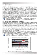
Страница 39: ...ensor Operation The plug in Battery Temperature Sensor BTS is used to determine the battery temperature around the batteries This information allows the multi stage battery charger to automatically adjust the battery charge voltages for optimum charging performance and longer battery life When the BTS is installed if the temperature around the BTS is below 77 F 25 C the absorb and float charge vol...

Страница 40: ...s The inverter will automatically restart when the battery falls to the High Battery Cut In HBCI level Refer to Table 3 1 to determine the HBCO and HBCI levels for your inverter model Info High battery voltage may be caused by excessive or unregulated voltage from solar panels or other external charging sources Overload During inverter and standby operation the inverter monitors current levels In ...

Страница 41: ...F switch there is a fault condition such as low battery high battery overload over temperature or an internal fault Refer to the Troubleshooting section to help diagnose clear the fault condition Slow flash blinks on once every 8 seconds Indicates float charging the inverter is in Standby mode the external AC power that is connected to the inverter s input is passing through the inverter and is po...

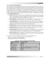
Страница 42: ...es when the inverter will turn off based on low battery voltage The inverter turns off automatically after the battery voltage has been below this setting for more than one minute This protects the batteries from over discharge and the AC loads from unregulated power brown outs 03 Batt AmpHrs This setting allows the user to input the battery bank size in amp hours which tells the charger how long ...

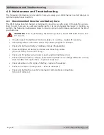
Страница 43: ...ng the following checks switch OFF both the AC and DC circuits Visually inspect the batteries for cracks leaks or swelling replace if necessary Use baking soda to clean and remove any electrolyte spills or buildups Check and tighten all battery holddown clamps if applicable Clean and tighten all battery terminals and connecting cables 10 to 12 ft lbf 13 6 to 16 3 N m Check and fill battery water l...

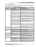
Страница 44: ...verter ensure cool air is available to pass through the inverter refer to the ventilation requirements in Section 2 1 3 AC overload condition The inverter has turned off because the connected loads are larger than the inverter s output capacity or the output wires are shorted Reduce the AC loads connected to the inverter or remove all AC output wiring and restart the inverter Internal fault This f...

Страница 45: ...lt the inverter will need to be reset To reset the inverter Press and hold the Power ON OFF pushbutton see Figure 4 1 for approximately fifteen 15 seconds until the Charging Inverting Status LED comes on and flashes rapidly once the rapid flashing has begun release the Power ON OFF pushbutton The Status LED will go off after the pushbutton is released After the inverter reset is completed press th...

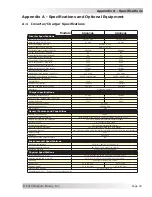
Страница 46: ...Rated Output AC amps 11 5 16 Charger Efficiency 87 85 AC Input Frequency Range 40 60 Hz AC Input Voltage Range 115 268 VAC Power Factor 0 95 General Features and Capabilities Transfer relay capability 30 AAC Five stage charging capability Bulk Absorb Float Equalize requires remote and Battery Saver Battery temperature compensation Yes 15 ft Battery Temperature Sensor standard Internal cooling 0 to...

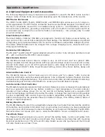
Страница 47: ...gs such as Inverter ON OFF Charger ON OFF Utility Power Breaker Setting AGS Control Meter Button Setup and Tech menus Advanced Remote Control The ME ARC50 Remote Control Panel uses an LCD screen and at a glance LEDs to provide operating information and allow advanced features to be configured requires Magnum inverters with advanced configurable features This LCD remote control also provides advanc...

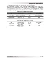
Страница 48: ...otechnical Commission s IEC wiring color codes The tables also list the labels that Magnum Energy applies to identify AC DC wiring usage in its inverters Table A 1 AC Wiring Color Codes Use Magnum Label Europe U S Canada Protective earth AC GROUND Green w yellow stripe Bare green Neutral out in NEUTRAL OUT NEUTRAL IN Blue White marked white Line single phase out in HOT OUT HOT IN Brown Black Table...

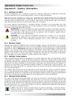
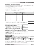
Страница 49: ...batteries best suited for the inverter installation and cost Use only the same battery type for all batteries in the bank For best performance all batteries should be from the same lot and date This information is usually printed on a label located on the battery B 3 Battery Temperature Battery performance of lead acid type batteries is greatly affected by extreme temperatures When a lead acid typ...

Страница 50: ...ed each day for all the loads Add the Average Daily Watt Hours Per Load together Total Daily Watt Hours Total Daily Watt Hours Total Amp Hours 3 Determine the battery Amp Hour capacity needed to run all the loads before recharging Divide the Total Daily Watt Hours by the nominal battery volt age of the inverter i e 24 volts and Multiply this by how many days the loads will need to run without havi...

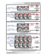
Страница 51: ...igure B 3 below four 6 VDC 200 AH batteries are combined into two strings resulting in a 12 VDC 400 AH battery bank Series Parallel Battery Wiring combines battery voltage and capacity 200 AH 6 VDC 200 AH 6 VDC 200 AH 6 VDC 200 AH 6 VDC 400 AH 12 VDC add voltage in series 6 VDC 200 AH 6 VDC 200 AH 6 VDC 200 AH 6 VDC 200 AH 12 VDC 400 AH 200 AH 12 VDC 200 AH 12 VDC add capacity in parallel add volt...

Страница 52: ... 200 AH 6 VDC battery 200 AH 6 VDC battery 200 AH Series String 6 VDC 6 VDC 6 VDC 6 VDC Parallel String 200 AH 200 AH 12 VDC battery 100 AH overcurrent protection to 24 VDC inverter total capacity 200 AH Series String 12 VDC 12 VDC 12 VDC battery 100 AH 12 VDC battery 100 AH 12 VDC battery 100 AH Series String 12 VDC 12 VDC Parallel String 100 AH 100 AH Series String 6 VDC 6 VDC 6 VDC 6 VDC Series...

Страница 53: ...sale itemized receipt 5 The original purchaser shall return the product prepaid to Magnum Energy in Everett WA After the completion of service under this limited warranty Magnum Energy will return the product prepaid to the original purchaser via a Magnum selected non expedited surface freight within the contiguous United States and Canada this excludes Alaska and Hawaii 6 This limited warranty is...

Страница 54: ...Magnum Energy Inc 2211 West Casino Rd Everett WA 98204 Phone 425 353 8833 Fax 425 353 8390 Web www magnumenergy com RD E Series Owner s Manual PN 64 0046 Rev A ...

Отзывы: