background image

5


L25

056


(2/13)


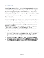
A.  Uncrate unit and put into place. The hitch pins securing burners must be removed. This 

will permit the burners to be readily removed for weekly inspection, cleaning and future 
service. 
 

B.  FOR INSTALLATION ON LEGS: A set of 4" legs is packed in the top section of the broiler 

(unless unit is specifically ordered without). A threaded receptacle is located near each 
corner base of the machine. Each leg has a similar mating thread. Raise unit sufficiently to 
allow legs to be screwed tightly into receptacles. Level the unit by adjusting bottom feet of 
legs. Unit must be level to perform properly. FOR INSTALLATION WITH CASTERS: This 
installation shall be made with a connector that complies with the Standard for 

Connectors 

for Movable Gas Appliances, ANSI Z21.69

 • 

CSA-6.16, 

and with a quick-disconnect 

device that complies with the Standard for 

Quick-Disconnect Devices for Use With Gas 

Fuel, ANSI Z21.41 

 CSA-6.9.


  Provide an adequate means of restraint without depending on the gas connector, the 

quick-disconnect device or its associated piping to limit the appliance movement. 


  The restraint (i.e. heavy gauge chain or cable) should be 1000# (4.45 kN) test load and 

should be attached to the building structure by some substantial means, such as the 
use of anchor bolts into concrete, or lag screws into studs in wooden structures. The 
opposite end of the restraint should be affixed solidly to the base of the unit at the back 
where it will not become pulled out or cause damage to the appliance. 

If disconnection of this restraint becomes necessary at any time, make sure it is 
reinstalled after the unit is placed in its original position 

and before 

the unit is placed in 

operation. 


           CAUTION! 


Only two of the four casters supplied have brakes. Be sure to install the two casters with 
brakes at the 

front of the unit. 

NOTE

Front brakes should be locked before unit is placed 

in operation. 


C. 

COUNTER MODELS: All counter equipment is to be sealed to the counter to 
comply with applicable sanitation standards. A bead of silicone sealant, 
approximately ½" wide, is to be applied to the bottom of the unit approximately ¼" in 
from the front, back and side edges. 


We 

suggest a Dow Corning®, GE® or Permatex® silicone ‘RTV’ adhesive sealant or 

equivalent. (See NSF 

Basic Criteria C-2 

for details). 


D.  After installation retain manual for future reference. 


Содержание 24

Страница 1: ...H 03302 0501 509 ROUTE 3A BOW NH 03304 603 225 6684 FAX 603 225 8497 www magikitchn com IMPORTANT FOR FUTURE REFERENCE Please complete this information and retain this manual for the life of the equip...

Страница 2: ...ng on the gas connection Single appliances equipped with legs must be stabilized by installing anchor straps All appliances equipped with casters must be stabilized by installing restraining chains If...

Страница 3: ...Specifications 6 3 GAS HOOK UP 7 4 GAS SETTINGS 8 5 LIGHTING INSTRUCTIONS 8 A FOCUS SERIES MODELS 8 6 INITIAL SET UP 9 7 CLEANING AND MAINTENANCE 11 8 IMPORTANT OPERATION INSTRUCTIONS RECAP 12 9 TYPI...

Страница 4: ...National FueI Gas Code ANSI Z223 1 NFPA 54 or Natural Gas and Propane Installation Code CSA B149 1 as applicable In AUSTRALIA this appliance must be installed to the requirements of the AS NZS5601 1...

Страница 5: ...e appliance movement The restraint i e heavy gauge chain or cable should be 1000 4 45 kN test load and should be attached to the building structure by some substantial means such as the use of anchor...

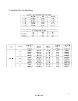
Страница 6: ...NE 2 5 10 0 363 Type Model Height with Legs in cm Width in cm Depth in cm Shipping Weight lb kg Total Cook Area in2 cm2 FOCUS 24 21 625 54 928 24 000 60 960 30 436 77 307 210 95 2 556 370 3589 477 36...

Страница 7: ...warranty B The manifold pressure must be maintained at the pressure marked on the serial plate 4 w c for natural gas and 10 w c for propane gas C Use pipe joint compound that is suitable for the LP ga...

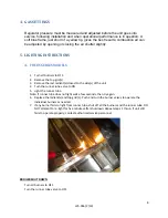
Страница 8: ...emove the last radiant s closest to the side s of the unit 4 Turn the runner tube valve to ON 5 Light the runner tube Note If runner tube does not light wait a few seconds then try again 6 Replace the...

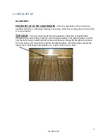
Страница 9: ...up properly TOP GRID Your top cooking grid has two positions either flat or slightly tilted Whenever you are broiling may use one the tilted position This allows grease to drain into the front trough...

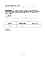
Страница 10: ...l produce the proper searing effect FLARE UP A certain amount of flare up is desirable when you are charbroiling in order to flavor your products However excess flare up will burn your products and le...

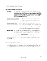
Страница 11: ...clean them but be sure to remove all residues before you resume cooking operation The grease collection pan should be emptied daily and the grease disposed of properly WATER TUB The water tub is desig...

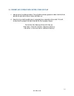
Страница 12: ...to the front grease trough and reduce smoke and flare up 2 Keep the top cooking grids clean especially the underside of the rods This will insure that the grease will drain toward the front grease tro...

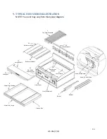
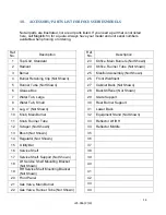
Страница 13: ...Grid Standard 2 Radient 6 Grease Box 7 Water Tub Large 8 Water Tub Medium 10 Knob Main Burner 11 Knob Runner Tube 15 Utility Bar 16 Service Shelf 20 Front Panel 21 Gas Valve Main Burner 29 Grate Supp...

Страница 14: ...Burner 11 Knob Runner Tube 12 Scraper Not Shown 13 Brush Not Shown 14 Regulator Not Shown 15 Utility Bar 16 Service Shelf 17 Service Shelf Support Not Shown 18 LH Service Shelf Mounting Bracket Not S...

Страница 15: ...his warranty includes travel time not to exceed two 2 hours and mileage not to exceed one hundred 100 miles round trip This warranty does not cover any defect due to or resulting from ordinary wear an...

Страница 16: ...d included in the owner s document package Upon the return of the registration card the warranty period will commence as provided above If such registration card is not returned then the warranty peri...

Страница 17: ...17 L25 056 2 13 NOTES...

Страница 18: ...18 L25 056 2 13 NOTES...

Страница 19: ...19 L25 056 2 13 NOTES...

Страница 20: ...ide Website www magikitchn com In the event of problems with or questions about your equipment please contact the MagiKitch n Authorized Service and Parts representative ASAP covering your area or con...

Отзывы: