


Page 8 of 22
508197-01
Issue 2137
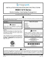
Figure 6. Positioning Vent Pipe Extension
Outdoor Fan
0
Vent Extension
Clearance Holes*
* The clearance holes are not marked
on the actual vent extension.
6. Position the vent pipe at the center of the metal wire
grille when using polypropylene louvers. The vent
pipe should have a slight downward slope to allow any
moisture to drain away from the unit as well as being
centered on the metal wire grille.
Ductwork
Ductwork should be designed and sized according to the
methods in Manual Q of the Air Conditioning Contractors
of America (ACCA).
Check unit supply and return air openings for debris
before making ductwork connections.
It is recommended that supply and return duct connections
at the unit be made with flexible joints. If flexible ducts are
used, a 6” sheet metal starter collar is required.
The supply and return air duct systems should be fabricated
per the designed CFM and static requirements of the job
Ductwork should not be sized to match
the dimensions of the duct connections on the unit.
The return duct should be sealed to the unit casing and
terminate outside the space containing the unit.
Do not screw into the side of the drain pan or the indoor
coil, which is located above the installation bracket.
CAUTION
Figure 7. Securing Unit
Installation
Brackets
Remove and replace screw to secure bracket
(one each side)
Model
Gas Heating
Indoor
Blower
Speed
0.1 “w.c.
0.2 “w.c.
0.3 “w.c.
0.4 “w.c.
0.5 “w.c.
Rise
Range
(F°)
Mid
Rise
(F°)
SCFM
W
atts
HP
Temp Rise
SCFM
W
atts
HP
Temp Rise
SCFM
W
atts
HP
Temp Rise
SCFM
W
atts
HP
Temp Rise
SCFM
W
atts
HP
Temp Rise
0.75 T
on
15MGE4-12-091*P
15 - 45
30
TAP 1
(FAN)
430 46 0.06
---
370 50 0.07
---
320 53
0.07
---
265 57
0.08
---
200 62 0.08
---
TAP 2
(COOL)† 375 39 0.05
---
315 42 0.06
---
N/A N/A N/A
---
N/A N/A N/A
---
N/A N/A N/A
---
TAP 3
(COOL) N/A N/A N/A
---
N/A N/A N/A
---
440 83
0.11
---
390 87
0.12
---
340 92 0.12
---
TAP 4
(HEAT)* 365 35 0.05
31 300 39 0.05
37 240 42
0.06
47 N/A N/A N/A
N/A N/A N/A N/A N/A
TAP 5
(HEAT)
N/A N/A N/A N/A N/A N/A N/A N/A 460 83
0.11
24 415 88
0.12
27 370 98 0.13
30
24MGE4-12-091*P
25 - 55
40
TAP 1
(FAN)
430 46 0.06
---
370 50 0.07
---
320 53
0.07
---
265 57
0.08
---
200 62 0.08
---
TAP 2
(COOL)† 375 39 0.05
---
315 42 0.06
---
N/A N/A N/A
---
N/A N/A N/A
---
N/A N/A N/A
---
TAP 3
(COOL) N/A N/A N/A
---
N/A N/A N/A
---
440 83
0.11
---
390 87
0.12
---
340 92 0.12
---
TAP 4
(HEAT)* 445 48 0.06
40 390 53 0.07
46 340 56
0.08
53 N/A N/A N/A
N/A N/A N/A N/A N/A
TAP 5
(HEAT)
N/A N/A N/A N/A N/A N/A N/A N/A 530 102 0.14
34 480 108 0.14
37 440 114 0.15
41
N/A: Do not operate unit using this blower speed at this external static pressure.
† As shipped speed for Cooling operation. Blower speed must be field adjusted to speed Tap 3 for higher duct static applications.
* As shipped speed for Heating operation. Blower speed must be field adjusted to speed Tap 5 for higher duct static applications.
# As shipped speed for Low Stage Cooling operation (low duct static).
Table 4. Blower Performance (208V or 230V)
Содержание MGE4-12 Series
Страница 20: ...Page 20 of 22 508197 01 Issue 2137 Figure 12 Wiring Diagram MGE 0 75 Ton through 2 Ton Wiring Diagrams ...
Страница 21: ...508197 01 Issue 2137 Page 21 of 22 Figure 13 Wiring Diagram MGE 2 5 Ton ...
Страница 22: ...Page 22 of 22 508197 01 Issue 2137 Figure 14 Wiring Diagram MGE 3 Ton ...