magicpak MGE4-12 Series Скачать руководство пользователя страница 4

Page 4 of 22

508197-01

Issue 2137

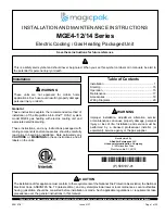
Figure 2. Minimum Clearances

Unit must be supported by platform, which must be 

level with sill plate of opening in exterior wall.

Platform (field supplied) - 

Supply Duct

Opening

Clearance to

Front of Unit

Closet Door / Access

Panel Opening

Minimum 30” wide

1” Min.

Side Clearance

Return Duct

Opening

Exterior Wall

1” Min. Side

Clearance

Closet Wall

Closet Wall

Top View

Exterior Wall

Wall Sleeve

Side Panel

(one each side)

Interior Wall

Minimum

Clearance

3/4" Plywood Riser

(supplied with wall sleeve)

Floor

Front of Unit

Sill Plate

4" Min.

Mounting Strap

(one each side;

supplied with unit)

Supply

Duct

Return

Duct

Condensate

Drain Trap

(field supplied)

Gas Piping

(field supplied)

Side View

IMPORTANT

The unit must be installed with approved 

wall sleeve and louver accessories for 

safe operation. Improper installations could 

result in property damage, personal injury, 

or death.

Supply Duct Clearances

Minimum Clearances to Combustible 

Materials

1

Front

Sides

Top

0”

0”

0”

1 Accessibility clearances take precedence.

Unit Clearances

Minimum Clearances 

[1]

Front

2

Sides

3

1”

1”

1 Accessibility clearances take precedence.

2 Clearance must accommodate field-installed 

condensate drain line / drain trap and gas line.

3 Additional clearance required if field-installed 

condensate drain line / drain trap is routing alongside 

unit.

NOTE: Consult local codes for other clearance 

requirements

Accessibility Clearances

The front of the unit must be accessible for service. A 

minimum clearance of 30” in front of unit is required for 

service. 

If the unit is enclosed, a door or access panel aligned with 

the front of the unit is the preferred method of providing 

access. The door or access panel opening must be a 

minimum of 30” wide (centered on the unit) and be as tall 

as the unit. 

Содержание MGE4-12 Series

Страница 1: ...must conform to the requirements of the National Fire ProtectionAssociation the National Electrical Code ANSI NFPA No 70 latest edition and any state provincial laws or local ordinances Local authorities having jurisdiction should be consulted before installation is made Such applicable regulations or requirements take precedence over the general instructions in this manual CAUTION P508197 01 P 50...

Страница 2: ... vapors and liquids in the vicinity of this or any other appliance Such actions could result in property damage personal injury or death WARNING Installation and servicing of air conditioning equipment can be hazardous due to internal refrigerant pressure and live electrical components Only trained and qualified service personnel should install or service this equipment Installation and service pe...

Страница 3: ...ring Connections Line Voltage Knockouts 7 8 and 1 1 8 Dia Top View 13 1 2 28 D 33 1 4 C Outdoor Coil Combustion Air Inlet Vent Pipe Termination 2 1 2 O D B 3 1 4 E Supply Air Opening Return Air Opening Outdoor Fan Discharge 32 3 8 Tool less Filter Access Condensate Drain 3 4 NPT Flame Inspection Sight Glass 3 4 28 Gas Pipe Connection 0 5 9 3 4 Compressor Gauge Ports Outdoor Fan Access Indoor Blowe...

Страница 4: ...essories for safe operation Improper installations could result in property damage personal injury or death Supply Duct Clearances Minimum Clearances to Combustible Materials1 Front Sides Top 0 0 0 1 Accessibility clearances take precedence Unit Clearances Minimum Clearances 1 Front2 Sides3 1 1 1 Accessibility clearances take precedence 2 Clearance must accommodate field installed condensate drain...

Страница 5: ...sidential garage it must be located or protected to avoid physical damage by vehicles The unit must be installed so that no electrical components are exposed to water This unit must be installed level to allow for proper drainage of the unit base pan and indoor drain pan CAUTION Wall Sleeve and Louver Installation Refer to installation instructions included with the wall sleeve and the louver alon...

Страница 6: ... enough that the seal is maintained Trim off excess bracket if applicable 5 Inspect the fit up of the unit to the wall sleeve Verify that the gaskets of the wall sleeve make a complete seal to the unit paying particular attention to top and bottom corners of unit to sleeve seal Caulk if needed Venting The venting system is an integral part of the appliance The venting system must not be modified i...

Страница 7: ...onnected to the venting system properly vents when tested as outlined above return doors windows exhaust fans fireplace dampers and any other gas fired burning appliance to their previous conditions of use CAUTION Locating Vent Pipe Extension Determining the length of the vent pipe extension is dependent upon which wall sleeve accessory is installed at the job site for each particular installation...

Страница 8: ...rew to secure bracket one each side Model Gas Heating Indoor Blower Speed 0 1 w c 0 2 w c 0 3 w c 0 4 w c 0 5 w c Rise Range F Mid Rise F SCFM Watts HP Temp Rise SCFM Watts HP Temp Rise SCFM Watts HP Temp Rise SCFM Watts HP Temp Rise SCFM Watts HP Temp Rise 0 75 Ton 15MGE4 12 091 P 15 45 30 TAP 1 FAN 430 46 0 06 370 50 0 07 320 53 0 07 265 57 0 08 200 62 0 08 TAP 2 COOL 375 39 0 05 315 42 0 06 N A...

Страница 9: ...15MGE4 12 181 P 15 45 30 TAP 1 FAN 470 54 0 07 400 59 0 08 345 63 0 08 290 67 0 09 235 70 0 09 TAP 2 COOL 670 118 0 16 625 123 0 16 565 131 0 18 525 136 0 18 N A N A N A N A TAP 3 COOL N A N A N A 765 184 0 25 730 191 0 26 675 201 0 27 630 206 0 28 TAP 4 HEAT 370 39 0 05 30 305 43 0 06 37 250 46 0 06 45 N A N A N A N A N A N A N A N A TAP 5 HEAT N A N A N A N A N A N A N A N A 460 92 0 12 24 415 9...

Страница 10: ... 26 370 90 0 12 30 24MGE4 12 241 P 25 55 40 TAP 1 FAN 450 49 0 07 400 52 0 07 345 56 0 08 285 59 0 08 235 65 0 09 TAP 2 COOL 815 206 0 28 780 210 0 28 750 215 0 29 720 219 0 29 690 224 0 30 TAP 3 COOL N A N A N A N A N A N A N A N A 850 283 0 38 820 287 0 38 785 286 0 38 TAP 4 HEAT 450 49 0 07 40 400 52 0 07 45 345 56 0 08 52 N A N A N A N A N A N A N A N A TAP 5 HEAT N A N A N A N A N A N A N A N...

Страница 11: ... A N A N A N A N A N A N A 930 325 0 44 900 328 0 44 TAP 4 HEAT 600 80 0 11 45 560 84 0 11 48 515 89 0 12 52 475 93 0 12 56 N A N A N A N A TAP 5 HEAT N A N A N A N A 705 136 0 18 38 670 141 0 19 40 635 146 0 20 42 600 151 0 20 45 48MGE4 12 301 P 35 65 50 TAP 1 FAN 490 55 0 07 465 65 0 09 435 72 0 10 415 81 0 11 390 89 0 12 TAP 2 COOL 930 239 0 32 900 243 0 33 885 250 0 34 835 256 0 34 805 262 0 3...

Страница 12: ... 715 234 0 31 50 3 Ton 60MGE4 14 361 P 40 70 55 TAP 1 COOL 704 126 0 17 664 131 0 18 626 136 0 18 592 141 0 19 553 147 0 20 TAP 2 COOL 1020 307 0 41 980 313 0 42 940 314 0 42 900 318 0 43 865 323 0 43 TAP 3 COOL N A N A N A N A N A N A N A N A 965 333 0 45 930 338 0 45 890 344 0 46 TAP 4 HEAT 825 175 0 23 54 790 179 0 24 57 755 185 0 25 59 720 191 0 26 62 690 197 0 26 65 TAP 5 HEAT 935 240 0 32 48...

Страница 13: ...e necessary to change a wire connection on unit transformer from 240 volt terminal to 208 volt terminal as shown on the wiring diagram Use wiring with a temperature limitation of 75 C minimum Run the 208 or 230 volt single phase 60 hertz electric power supply through a fused disconnect switch and connect to the unit as shown in the unit s wiring diagram The unit must be electrically grounded in ac...

Страница 14: ...auge Connection field supplied Filter Access Pipe connections must be tight and a non hardening pipe compound resistant to liquefied petroleum gases must be used Connect the gas pipe to the gas pipe connection providing a ground joint union as close to the gas pipe connection as is possible to facilitate removal of controls and manifold Provide a drip leg on the outside of the furnace A manual shu...

Страница 15: ...ustion air inducer shut off 7 Supply air blower will shut off 120 seconds later If the burners should fail to ignite the ignition control will try to ignite the burners a total of three times Should the burners fail to ignite within the three trials for ignition the ignition control will lock out for 1 hour before beginning another ignition cycle To reset the control turn the thermostat down or of...

Страница 16: ... spud size is installed and properly adjust the manifold pressure using a manometer Typical manifold set point for installations is 10 0 W C Adjustments Cooling Section No adjustments are required or should be attempted regarding any of the components of the cooling system The system should be checked for loose or missing wiring Blower The unit contains a constant torque ECM blower motor with dedi...

Страница 17: ...er Wash filter in soap or detergent water and replace after filter is dry Outdoor Coil Foreign material should not be allowed to accumulate on the outdoor coil surface or other parts in the air circuit Rollout Switch If for any reason the heat exchanger were to become blocked there is a temperature sensitive switch located above the burners that will turn off the burners After correcting the probl...

Страница 18: ...The unit must be installed with approved wall sleeve and louver accessories for safe operation Improper installations could result in property damage personal injury or death WARNING Refer to Table 9 for dimension information B 29 1 8 Required Wall Opening C Maximum Wall Thickness Exterior Wall 16 A 16 5 8 29 Wall Sleeve Figure 11 Motors The indoor and outdoor fan motors are permanently lubricated...

Страница 19: ... 32 3 4 32 7 8 10 14 ASLEEVE12 2 ASLEEVEXT4 2 ALVRAL 7 32 3 4 32 7 8 12 16 ASLEEVE6 5 ALVRAL 3 ALVRALC 3 45 45 1 8 6 ASLEEVE8 5 ALVRAL 3 ALVRALC 3 45 45 1 8 8 ASLEEVE10 5 ASLEEVEXT4 3 ALVRAL 3 ALVRALC 3 45 45 1 8 10 14 ASLEEVE12 5 ASLEEVEXT4 3 ALVRAL 3 ALVRALC 3 45 45 1 8 12 16 ASLEEVE6 5 ALVRP MGE 3 45 45 1 8 6 ASLEEVE8 5 ALVRP MGE 3 45 45 1 8 8 ASLEEVE10 5 ASLEEVEXT4 3 ALVRP MGE 3 45 45 1 8 10 1...

Страница 20: ...Page 20 of 22 508197 01 Issue 2137 Figure 12 Wiring Diagram MGE 0 75 Ton through 2 Ton Wiring Diagrams ...

Страница 21: ...508197 01 Issue 2137 Page 21 of 22 Figure 13 Wiring Diagram MGE 2 5 Ton ...

Страница 22: ...Page 22 of 22 508197 01 Issue 2137 Figure 14 Wiring Diagram MGE 3 Ton ...

Отзывы: