9
Owner’s Manual
Owner’
s Manual
13. Press
AUX SENDS 1
in the V-POT CONTROL area
(Figure 2-3).
14. Increase the Aux 1 level on channel 1 using the
V-Pot.
15. Press the
AUX MSTR
QuickMix button (Figure 2-
4).
16. Adjust Aux 1’s master level with its correspond-
ing QuickMix knob (see the Aux Master screen in
Figure 2-5).
You should hear your mic in the monitor speaker
attached to Aux 1.
Engage and adjust the variable high-pass
filter
17. Press
HPF
in the V-POT CONTROL area (Figure
2-2). This assigns the high-pass filter to the channel
V-Pots.
18. Engage the high-pass filter for channel 1 by pressing
its V-Pot knob so the bottom red LED lights.
19. Rotate the V-Pot to adjust the filter in the range
20–400 Hz to remove unwanted low frequencies.
20. To view the frequency range, select channel 1 and
press the QuickMix
EQ
button.
The Touchscreen now displays the HPF frequency
range.
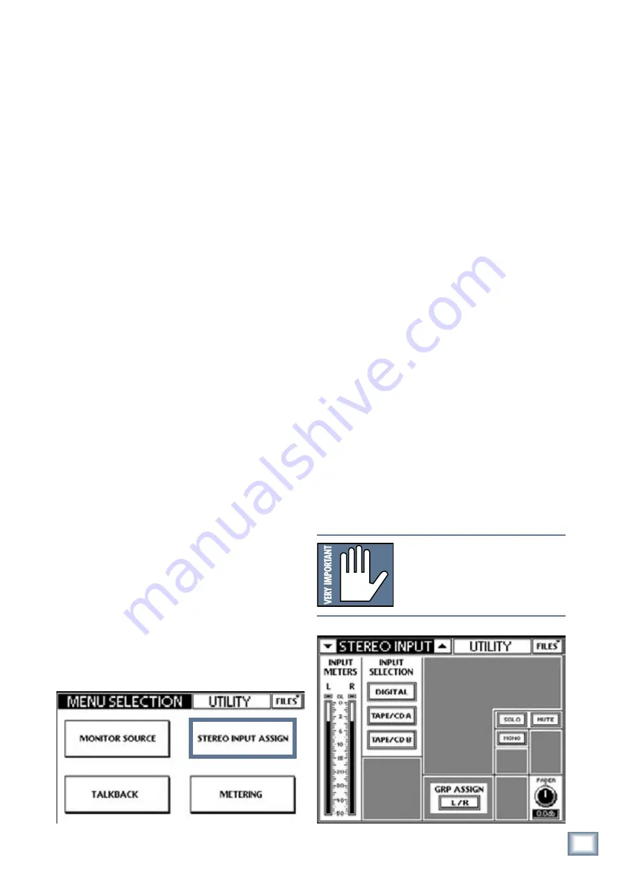
2.3 Connect a CD/Tape Device
This section illustrates how to connect a CD/tape
device to the dedicated
CD/ TAPE A
or
B
connectors
(A = RCA, B = TRS), and to channels 23/24 to demon-
strate stereo linking and channel strip processing.
Connect CD to CD/Tape input
1. Connect the CD player into CD/TAPE A or B
(Figure 2-1).
2. Press the
UTIL
button (Figure 2-4).
3. Touch
STEREO INPUT ASSIGN
on the Touch-
screen (Figure 2-6).
4. Touch
TAPE/CD A
or
TAPE/CD B
in the INPUT
SELECTION area (Figure 2-6).
5. Select
L/R
in the GRP ASSIGN area to route the stereo
source to the
LEFT
and
RIGHT MAINS
outputs.
6. Adjust
MUTE
and
SOLO
from the Touchscreen.
7. Adjust the stereo input fader to desired level from
its QuickMix knob.
Connect CD to channels 23 and 24
1. Move the
CD
to the channel 23 and 24
LINE
con-
nectors.
2. Set the
LINE
switch to the down position (line level).
3. Press and hold channel 23
and
24’s
SELECT
switches until the
Link Channels
dialog appears in
the Touchscreen.
4. Touch
OK
to approve the channel linking.
5. Press the
PAN
button in the V-POT CONTROL area
(Figure 2-3).
6. Turn channel 23’s V-Pot hard left. Channel 24 auto-
matically pans in the opposite direction. Pretty cool!
7. Activate the
SOLO
button above the fader on either
channel to solo. Because PFL is engaged, the linked
channel does not also solo.
8. Adjust the channel’s
GAIN
knob and watch the
meters to the right of the Touchscreen.
The level should be between -7 and -10 dBFS.
9. Repeat steps 7 and 8 for the other channel in the
linked pair.
NOTE:
Stereo linking always operates on a
consecutive odd/even channel pair. The odd
channel’s parameters are copied to the even
channel except Pan, which is inversely linked
(i.e., hard left on odd channel translates to
hard right on even channel).
Figure 2-6 Stereo Input Assign


