DX810 – 27
The input level meter indicates the level of the
input signal as it comes out of the analog to digital
converters and shows the level in dBFS. If the red
0 dB portion is lit, then the signal level is above
–2 dBFS and close to clipping. Note that the meter
indicates the signal level before any processing or
digital gain stages. If the signal is clipping, or is too
low, adjust the signal level at the source, or use the
trim controls on the rear panel of the DX810.
When a group is selected, click the
SELECT
button to assign the input to the selected group.
The assigned group fader then affects the signal
level for that input to all ten outputs. Click the
SELECT
button when the gate or compressor
windows are showing to adjust the processing
options for that input.
Click the mute (
M
) button to mute the input
signal to all ten outputs.
Ctrl+click the (
M
) button to engage the enable
function. The blue (
M
) button changes to a gray (
E
)
to indicate the enable function is active. This mutes
the input signal normally, and unmutes it when the
enable button is active. Ctrl-click the enable (
E
)
button to change back to the mute function.
Note:
When the enable function is engaged,
logic inputs, outputs, and remotes that are
programmed to activate/deactivate/indicate the
mute function now control (or are controlled by) the
enable function.
Click the solo (
S
) button to isolate the input
signal in the mix. When an input solo button is
engaged, the remaining inputs are automatically
muted. This is useful for troubleshooting and
listening to each input individually.
Use the name box at the bottom of the Input
Section to enter a name for the input (e.g., CD Left,
CD Right, Vocal, Guitar, etc.), up to 32 characters.
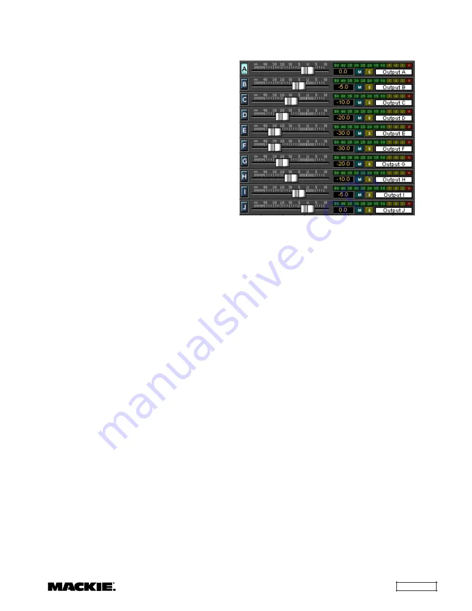
Output Section
The Output Section includes the ten output
faders along with their associated bargraph output
level meters. This section also includes numerical
gain display, mute and solo buttons, and name box.
Use the output faders to adjust the final output
level of the signal. Adjust the output faders so that
the associated output meter indicates around the
–10 and –7 dB positions when a normal signal is
going to that output. This provides the best signal-
to-noise ratio for the output stage. It is okay for the
–4 and –2 LEDs to blink occasionally on musical
peaks. However, avoid allowing the red 0 dB
indicator to light, which indicates that the signal is
within 2 dB of clipping.
Note that the meter indicates the signal level
after the output signal processing (i.e., Graphic EQ
or Parametric EQ, Compressor, Crossover). If
adjustments are made to the output processors, the
output fader may need to be readjusted. This is to
compensate for an increase or decrease in gain
through the processors.
Click the mute (
M
) button to mute the output signal.
Ctrl+click the (
M
) button to engage the enable
(
E
) function. This mutes the output signal normally,
and unmutes it when the enable button is on
(active). Ctrl+click the enable (
E
) button to change
back to the mute function.
Note:
When the enable function is engaged,
logic inputs, outputs, and remotes that are
programmed to activate/deactivate/indicate the
mute function now control (or are controlled by) the
enable function.
Click the (
S
) button to solo the output. This
mutes all the outputs except the soloed output.
This is useful for troubleshooting and listening to
each output individually.
Click the letter button (
A-J
) when a group is
selected to assign the output to the selected group.
Click the letter button when a processing window is
showing (except Gate and Input EQ) to adjust the
processing options for that output.
Use the box to the right of the Output Section to
enter a name for the output (e.g., Main Left, Control
R), using up to 32 characters.


