6
Not Used
Not Used
7
Busy Common
Common for the busy relay
8
Busy Relay
Activates when system is recording or
playing a message.
9
Playing Common
Common for the Playing Relay.
10
Playing Relay
Activates when system is playing.
11
Recording Common
Common for the Recording Relay.
12
Recording Relay
Activates when the system is
recording.
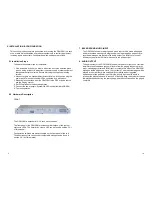
3. PAGE STACKING, FEEDBACK ELIMINATION OPERATION
The OPM-3SM offers 3 channels of page stacking, intended for busy paging
systems with multiple inputs. Each channel performs the following functions:
1. It eliminates feedback by recording the incoming page(s), then playing them
back
after the user “hangs up”, eliminating any feedback loop.
2. It is able to repeat each page allowing for better intelligibility in a noisy
environment.
3. It is capable of stacking up to 16 incoming pages per channel by recording
incoming pages while playing back previously recorded ones on a first-in first-
out basis.
Constraints:
-Each page is allowed a maximum of 1 minute recording time. Pages exceeding
this will be aborted and a busy back tone is generated.
-Recordings that reach the end of memory are considered incomplete. These
pages are aborted and a busy back tone is generated. If the memory is filled
and a new recording command is offered, the OPM-3SM will not go into record
mode and a busy back tone will be output to tell the user that the system not
available.
-The recorded message must be a minimum of one second in length. Any
message shorter than this will be aborted.
-The OPM-3SM aborts pages that are comprised of 3 or more seconds of
silence. The page is deleted and a busy back tone is generated.
Other important features include the ability to Record/Regenerate, or Block
DTMF tones for use in zone controller applications.
The OPM-3SM is designed to run in both Automatic and Manual modes. For
paging applications the Automatic mode is the most widely used. This mode
requires minimum installation time sinc
e it is the factory’s default setup. RJ12
connectors are used for Audio inputs and outputs. Where logical, certain control
signals are also provided on the individual RJ12 connectors associated with each
input.
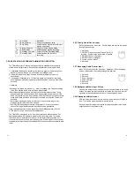
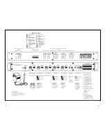
2.2.5 Priority Audio/Control Input
RJ12 style connector, 6 position. Priority pages are input to the device
through this connector.
1. Not used.
2. PRIORITY input, connect to Ground (Pin 5) to
activate. Priority active for duration of closure.
3. PRIORITY Audio, ring/return.
4. PRIORITY Audio, tip/signal.
5. Ground. (power return).
6. Not used.
2.2.7 Messaging Audio/Control Input
Input, RJ12 style connector, 6 position. Operation of the messaging
portion of the system is provided through this interface.
1. Not used.
2. Not used.
3. Audio, ring/return.
4. Audio, tip/signal.
5. Not used.
6. Not used.
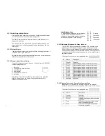
2.2.9 Background Music Input Volume
Controls the background music input volume level delivered to the audio
output. Adjusting this input clockwise increases the level, and counter-
clockwise rotation decreases the level of the background music.
2.2.10 Background Music Input
RCA jack, Input audio level should be set to a nominal level of 0dBv, or
less. Tip is audio signal and sleeve is audio return.
Any audio input at this port will be fed through the system to the audio
output whenever the system is idle.
13
6
Содержание OPM-3SM
Страница 12: ...9 10...


