2.2.11 Audio Output Mode Switch
A two position slide switch allows the user to configure the audio output
to match the needs of their downstream equipment.
The RIGHT position sets the output to line level (+4dB/600ohm). Use
this position as default.
The LEFT position sets the output to power level (500mW/8ohm). Use
this for longer runs, or if not enough level can be reached with the line
level output.
2.2.12 Output Volume
Controls the audio output volume level delivered to the paging system. It
is shipped with 1:1 gain factory set.
Adjusting this input clockwise increases the level, and counter-clockwise
rotation decreases the level of the device
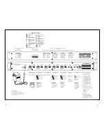
2.2.13 System Audio/Control Output
Output, RJ12 style connector, 6 position. All audio from the OPM-3SM
is output through this port
1. Not used.
2. Playing Relay, Normally Open.
3. Audio Return.
4. Audio Signal.
5. Playing Relay, Common.
6. Not used.
The playing relay contacts available on this connector are paralleled
with the connections on the Paging Control and Status Auxiliary
Interface, positions 9 and 10.
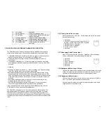
Delay Between Plays
To make the page sequence more intelligible,
a pause can be inserted between each
message in the playback sequence as well as
between any repeats of each message.
11
12
*1 second
3 seconds
5 seconds
10 seconds
2.2.15 Messaging Playback Auxiliary Interface
Top row of 12 inputs on the Auxiliary Interface. This interface allows
playback of pre-recorded messages through a momentary closure
(100ms). Each closure between a Play input and Ground will play the
corresponding message one time. Multiple closures on a single input or
several inputs will queue the messages and the system will play them in
the order received.
12 position Euro-style, two piece, pluggable type.
Pin
Name
Description
1
Ground
Common
2
Play 1
Plays message 1 when connected to ground
3
Play 2
Plays message 2 when connected to ground
4
Play 3
Plays message 3 when connected to ground
5
Play 4
Plays message 4 when connected to ground
6
Play 5
Plays message 5 when connected to ground
7
Play 6
Plays message 6 when connected to ground
8
Play 7
Plays message 7 when connected to ground
9
Play 8
Plays message 8 when connected to ground
10
Play 9
Plays message 9 when connected to ground
11
Play 10
Plays message 10 when connected to ground
12
Not Used
Not Used
2.2.16 Paging Control and Status Auxiliary Interface
Bottom row of 12 inputs on the Auxiliary Interface. Allows manual
access to many of the common inputs and status outputs of the system.
12 position Euro-style, two piece, pluggable type.
Pin
Name
Description
1
Ground
Common
2
Not Used
Not Used
3
Priority
Initiates priority page when connected
to ground.
4
Stop
Stops any currently playing message
when connected to ground.
5
Play
Plays next message in queue when
connected to ground.
7
12
Содержание OPM-3SM
Страница 12: ...9 10...


