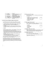
2.2.1.4 Paging Input Channels (Channel 1,2,3)
Off Hook LED
- Yellow, indicates the priority channel is being accessed
via a phone circuit. (Loop current flowing)
Audio Sense LED
- Yellow, indicates audio signal is present on that
particular Page port.
Record LED
- Red, indicates that the particular Paging channel is
recording a message.
Play LED
- Green, indicates that the particular Paging channel is
playing a message.
2.2.2 Power Input
Unit requires 12 VDC @ 1amp via the barrel connector. Only use the
factory supplied power pack. The chassis is connected to negative side
of power supply.
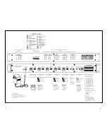
2.2.3 Audio/Control Input, Paging Channels 1 - 3
RJ12 style connector, 6 position. All pages to be recorded are input to
the device through these connectors
1. Abort, stops and deletes the recording when
connected to Ground (Pin 5).
2. Record input, connect to Ground(Pin 5) to
activate. Unit records for duration of closure.
3. Audio, ring/return.
4. Audio, tip/signal.
5. System Ground, (power return).
6. Not used.
2.2.4 Port configuration Switch, Paging Channels 1
– 3, Priority
Input, Message Input
A three position slide switch is provided for each of the five inputs
from the paging system: Channel 1, 2, 3, Priority, and Message.
The switch configures the particular port to meet the requirements
of the paging system.
Analog Station
- LEFT Position. Impedance 900 ohm, voltage for ring
trip 75 - 105V (20 - 60Hz).
Dry Loop
- Center Position. Configures audio input for 600ohm, line
level (-10dB nominal).
Loop Start
- RIGHT Position. Configures priority audio input for
900ohm and supplies 24VDC talk battery. Compatible with loop start
trunk ports.
3.1 Page Recording
Upon receiving a valid recording signal, the OPM-3SM will start recording at
the beginning of the memory until the page is complete. While this page is
playing, new pages can still be recorded. Multiple pages will be recorded in
series until the playing message has completed its play routine.
Multiple channels may be recording incoming pages at the same time.
Playback order of pages is based on when the recording process is
complete. For example, if a long message is being recorded on channel 1,
and during that process a short message is recorded and completed on
channel 2, the playback order will be the message on channel 2 then the
message on channel 1.
3.2 Record Activation Methods
There are several methods to initiate automatic record mode on the
OPM-3SM. The activation mode will be selected by the Setup Switches upon
power up. It cannot be changed during normal operation.
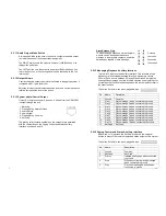
Loop Current detect
- Setup Switches 1=OFF, 2=OFF
If an input’s input configuration switch is set for loop start mode, the OPM-
3SM will source the talk battery(24VDC) to the ring and tip, and then sense
the loop current when phone goes off hook and start the recording process
for the duration of the page. Valid for Analog Station and Loop Start modes.
Audio Sense
- Setup Switches 1=OFF, 2=ON
For record activation without a separate switch closure or loop current. The
OPM-3SM will start recording when the audio sensor goes active and will
stop when the audio sensor is inactive for three seconds. Valid for Analog
Station, Loop Start and Dry Loop modes.
DTMF Activation
- Setup Switches 1=ON, 2=OFF
For record activation without a separate switch closure and perhaps noisy
audio lines. The OPM-
3SM will start recording when it “sees” a valid DTMF
tone and will stop when the audio sensor is inactive for three seconds. Valid
for Analog Station and Loop Start modes. The DTMF tone used to activate
the recording will be stripped and not output when the message is played.
Manual Recording
- Available in all modes - Typically associated with Dry
Loop mode, this method enables the OPM-3SM to begin recording with a
switch closure between pins 2 and 5 of the RJ12 connector of a particular
channel.
3.3 Playback
The OPM-3SM can be configured to automatically playback pages after their
record process has completed. This mode is configured by setting Setup
Switch 8 to OFF.
The OPM-3SM may be configured for manual or switch closure
playback(Setup Switch 8=ON) when you want full control of when pages will
playback. Playback is triggered via a momentary closure(100ms) between
pins 1 and 5 of the Paging Control and Status Auxiliary Interface.
5
14
Содержание OPM-3SM
Страница 12: ...9 10...


