


5
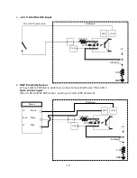
Description of the interface assemblies
1.
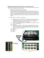
Charge pump circuit and enable signals
When there is no E-stop condition and the Mach3 software based control is running
properly, Mach3 outputs a steady pulse stream to the IO6 breakout board. The IO6
receives this pulse stream and sends an enable signal to every axis mod jack
connector, on mod jack pin #4. It also enables all outputs of the IO6. If this pulse
stream is interrupted, the IO6 will correspondingly disable all outputs from the IO6.
This safety circuit prevents spurious outputs from the PC from producing unexpected
results.
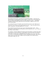
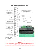
The charge pump circuit energizes a relay that provides a pair of bare relay contacts,
and +5V & +24V enable signal for system integrators to use to implement other safety
measures. We also provide direct access to the charge pump signal. This phoenix
terminal is located on the Auxiliary Terminal Block. (See Figure 2)
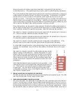
The charge pump input can be over-ridden by switching dip switch #4 to the “closed”
position (See Figure 3). This removes the safety provision of the system thus a machine
must not be operated with the charge pump disabled. This provision is only made
available for the use of the systems integrator’s use in setup or troubleshooting.
**************WARNING**************
Use of the IO6 in a machine application with the Charge pump
disabled is forbidden. Computer based controls running the
Windows operating system may encounter unexpected
interruptions due to outside influences and computer failures. The
Charge pump circuit is a safeguard against these occurrences.
Disabling it can allow for DEATH, INJURY or serious PROPERTY
DAMAGE.
**************WARNING**************
Figure 3
C
lo
se
d
O
p
en
ed
5
4
3
2
1
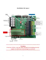
Figure 2
Charge pump output bare
relay contacts (CP/CP)
Auxiliary Terminal
Charge pump pulse stream. Port# 2 pin 17
Charge pump enabled output (+5v) / (+24v)
Содержание IO6 V4.0
Страница 2: ...2 This page was intentionally left blank...
Страница 24: ...21...


