


17
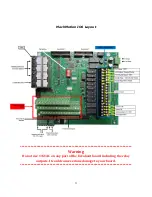
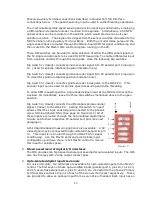
and 15) can be configured as general purpose inputs through the phoenix terminals so
labeled. For example, inputs 12, 13 and 15 can be used for spindle control as
described under the section of this manual entitled Spindle control. See the
description of these features and the pertinent DIP switch settings in the paragraph
entitled Spindle control above. See page 7 Figure #13. These three inputs are limited
to 5v signal inputs and the three terminals below the input terminals of the Primary
Terminal Block provide the 5V source if needed.
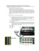
15.
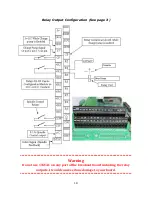
Relay outputs
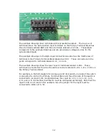
For noise immunity, the IO6 provides a PCB mounted bank of 8 relays used as outputs.
See page 15 Figure #11. The connections to the Relay bank PCB are found on the
Auxiliary Terminal Block. The output connections are labeled in pairs: +R2 R2, +R3 R3
etc.
The output pairs are dry contacts capable of handling 2 amps each. To set up in Mach3
go to Config/Ports and Pins/Setup and Axis Selection, Port 2 configuration table, then
deselect
Pins 2-9 as inputs.
Содержание IO6 V4.0
Страница 2: ...2 This page was intentionally left blank...
Страница 24: ...21...


