


4
IO6 General Description
MachMotion’s IO6 breakout board provides a flexible, plug-in-play interface for CNC controls
using PC based parallel port control software. The breakout board interfaces to the servo
drives and spindle relay outputs with RJ45 mod jacks and Phoenix screw terminals for
flexibility.
Features
•
Single unregulated 24 VDC supply power.
•
Digital differential and single ended TTL (Pulse and Direction) interfaces for motion control
for up to six axes.
•
2 Amp bare relay contact outputs.
•
Opto-isolated inputs.
•
Complete spindle speed control circuitry and spindle feedback.
•
Charge pump safety circuit integrated to control all outputs.
•
On board swi5V regulated power supply.
•
Drive enable can be configured at 5V, 24V, GND, or a user supplied voltage.
•
Total of 34 I/O.
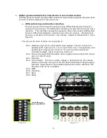
Input & Output List
•
12 - Outputs generally used for step and direction for 6 axes. If less than six axes are to
be controlled, some of these 12 outputs can be used for general purpose outputs.
•
10 - Inputs (1 input is typically used for spindle encoder input). These inputs can be
configured for 5V inputs, 12-24V inputs, PNP or NPN sensors.
•
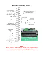
8 - 2 Amp 5-24V relay outputs.
•
2 - Spindle relay outputs.
•
1 - Analog output 0-10V.
•
3 - Charge pump outputs.
•
E-Stop circuit
•
Digitizing probe interface with 12V power supply.
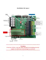
Use of this manual
This manual explains the functions of the IO6 in a logical progression. To understand how to
safely connect and use the IO6, it is important that the system integrator read and understand
the manual in its entirety before attempting to set up and use this I/O board.
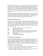
IO6 System Requirements
•
2 PC Parallel ports
•
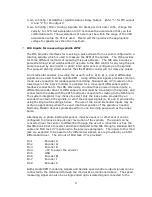
Power Requirements
+24 VDC filtered, regulated or unregulated
power is all that is required. The IO6 board
gen5 volts and +12 volt supplies for
user. (See Figure 1)
Figure 1
+24vdc
GND
Содержание IO6 V4.0
Страница 2: ...2 This page was intentionally left blank...
Страница 24: ...21...


