09
F5
F8 F7 F6
F4
F6
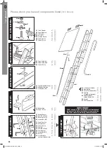
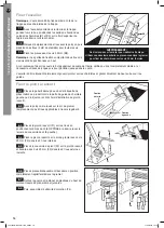
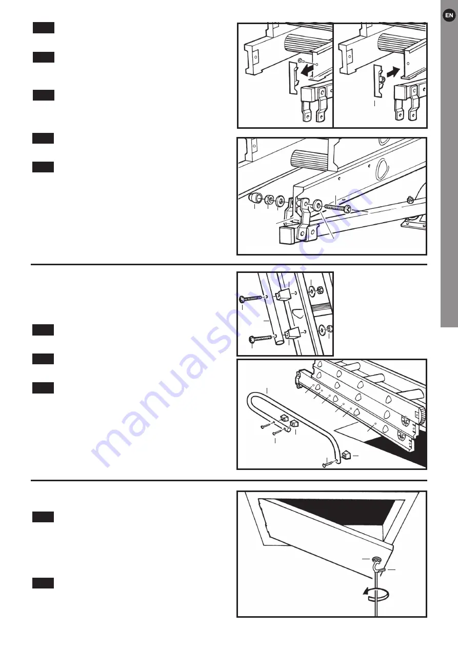
Handrail Assembly
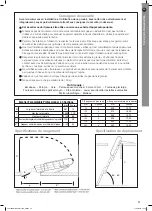
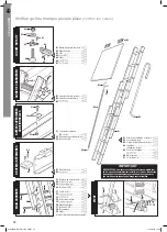
The handrail (G6) can be fitted to either side of the loft
ladder. It is advisable to fit the handle only after fitting
the power pivot arm.
Fix the handrail to your chosen side of the
rear frame.
Use 3 x spacers (E1), 60mm bolts (E2),
washers and nuts (E3 & E4) supplied.
You have a choice of 2 different handrail
heights which will be dependent on the amount of
“in-loft” handrail you require.
Check that all fixings for the whole assembly are fully
secure.
9.3
9.2
9.1
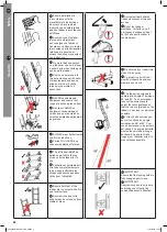
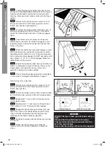
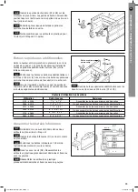
Locate the power arm linkage plates either
side of pivot tip (F4)/ladder stile and align all holes.
Secure the stile to the linkage plates using bolt
(F5), washers (F6), nut and nut cap (F7 & F8).
Ensure bolt (F5) and nut (F7) are tightened sufficiently
to allow the linkage to freely rotate without any
looseness.
DO NOT over-tighten the nut as this will restrict
smooth operation of the ladder system.
8.10
8.9
G3
A1
*
Position 1 fixes handrail in top position
** Position 2 fixes handrail in low position
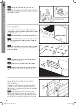
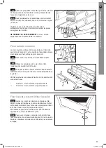
Operating the Ladder
Locate the plastic stowing hook/key (G3) into
one end of the stowing pole (G2) and push firmly to
ensure the plastic stowing hook/key (G3) is fully located
within the pole. Secure hook/key (G3) with screw (G7).
Push the plastic end plug (G4) into the opposite end of
the stowing pole (G2).
To open the trapdoor locate the key (G3) into
the slot in the catch operator (A1) and turn the catch
anti-clockwise until it reaches the travel stop and then
lower the trapdoor.
10.2
10.1
Installation
and
operating
instructions
G6
E1
E2
E2
E1
E3
E4
G6
E1
E2
E2
E1
E3
E4
E2
E1
E2
E1
G6
1*
1*
1*
2**
2**
2**
E2
E1
E2
E1
G6
1*
1*
1*
2**
2**
2**
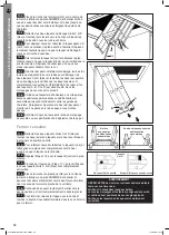
Position the ladder in its fully stowed (closed)
position carefully in the loft.
Remove the stud and plastic top tip from the
top of the required side stile of the rear ladder frame
and discard.
In their place fit Pivot Tip (F4).
8.8
8.7
8.6
F4
Position the ladder in its fully stowed (closed)
position carefully in the loft.
Remove the stud and plastic top tip from the
top of the required side stile of the rear ladder frame
and discard.
In their place fit Pivot Tip (F4).
8.8
8.7
8.6


