08
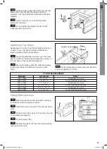
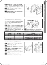
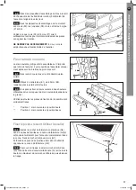
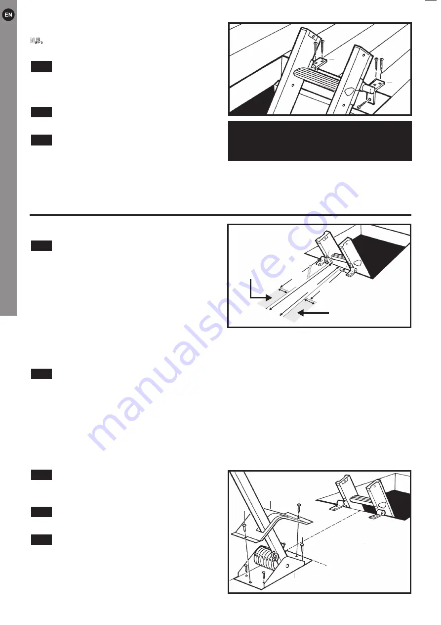
Fix the spring housing to the loft floor with 4 x
20mm screws (F3) through the 4 inner holes.
Place the housing cover (F2) over the spring
housing and fix down using 2 x 20mm (F3) screws
through the 2 remaining outer holes.
8.5
8.4
8.3
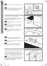
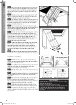
Installing the Power Pivot System
8.1
B3
B1
B2
If flooring material covers the top edge of the loft hatch frame ensure that it is completely stable and if necessary
use longer screws to penetrate the frame itself.
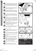
The ladder should now be free to swing from the hinges and slide freely up and down the guides.
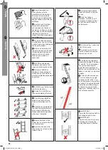
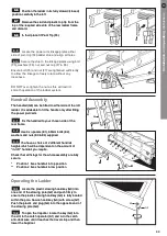
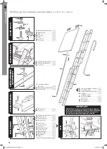
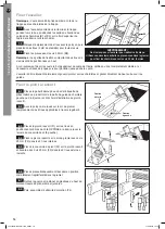
Installing the Ladder
N.B.
The ladder should be installed on the same side
of the trap as the trapdoor hinges.
With the ladder preferably centred in the
opening, and the trapdoor hanging down, locate the
hinge guide bracket arms (B1 & B2) on the top edge
of the loft hatch frame (see diagram).
Make guide holes with the bradawl then pre
drill pilot holes (2mm diameter) for all screws.
Fix using 35mm screws (B3).
N.B.
the bracket arms with two screw holes should be
on top.
7.3
7.2
7.1
Installation
and
operating
instructions
8.5
8.4
8.3
B3
B1
B2
Installing the Ladder
.
of the trap as the trapdoor hinges.
s
7.3
7.2
7.1
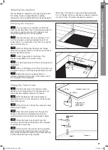
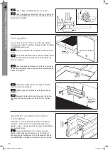
Using a bradawl mark the 6 fixing positions on to
the loft floor through the 6 applicable holes in the spring
housing (F1).
Decide which side of the ladder the power pivot
assembly will be fitted (left-hand or right-hand side) then
follow relevant instructions below marking the lines in the
directions as illustrated:
RIGHT HAND SIDE: Measure 28mm from inside (LH) face
of the right-hand hinge-guide bracket & mark a line
655mm long on the loft floor at 90° from the edge of the
opening. Next measure 435mm along the line you have
just marked from the loft opening & mark a new line
100mm across on the loft floor at 90°to the first line.
LEFT HAND SIDE: Measure 64mm from inside (RH) face of the left-hand hinge-guide bracket & mark a line
655mm long on the loft floor at 90° from the edge of the opening. Next measure 435mm along the line you have
just marked from the loft opening & mark a new line 100mm across on the loft floor at 90° to the first line.
Position the spring housing (F1) by following the relevant instructions below for the side of the ladder that
you have selected to fit the power pivot system:
RIGHT HAND SIDE:
Place the spring housing (F1) so the front left-hand corner is positioned where the two lines
that have been marked intersect. So the front face is positioned on the horizontal line you have marked on the loft
floor and the left-hand face is positioned on the vertical line marked on the loft floor. Ensure the arm points AWAY
from the loft opening (with slot in cover on the left-hand side).
LEFT HAND SIDE: Place the spring housing (F1) so the front right-hand corner is positioned where the two lines
that have been marked intersect. so the front face is positioned on the horizontal line you have marked on the loft
floor and the right-hand face is positioned on the vertical line marked on the loft floor. Ensure the arm points AWAY
from the loft opening (with slot in cover on the left-hand side).
8.2
F2
F3
F1
F3
F3
F2
F3
F1
F3
F3
For Right
Hand Fixing
For Left
Hand Fixing
100mm
100mm
435mm
655mm
435mm
655mm
435mm
655mm
435mm
655mm
WARNING:
Do Not stand on the ladder to do this. Either using a
second ladder, or from inside the loft space, secure
the hinges using six 35mm screws supplied.
64mm
28mm
LEFT HAND
FIXING EXAMPLE


