background image

36

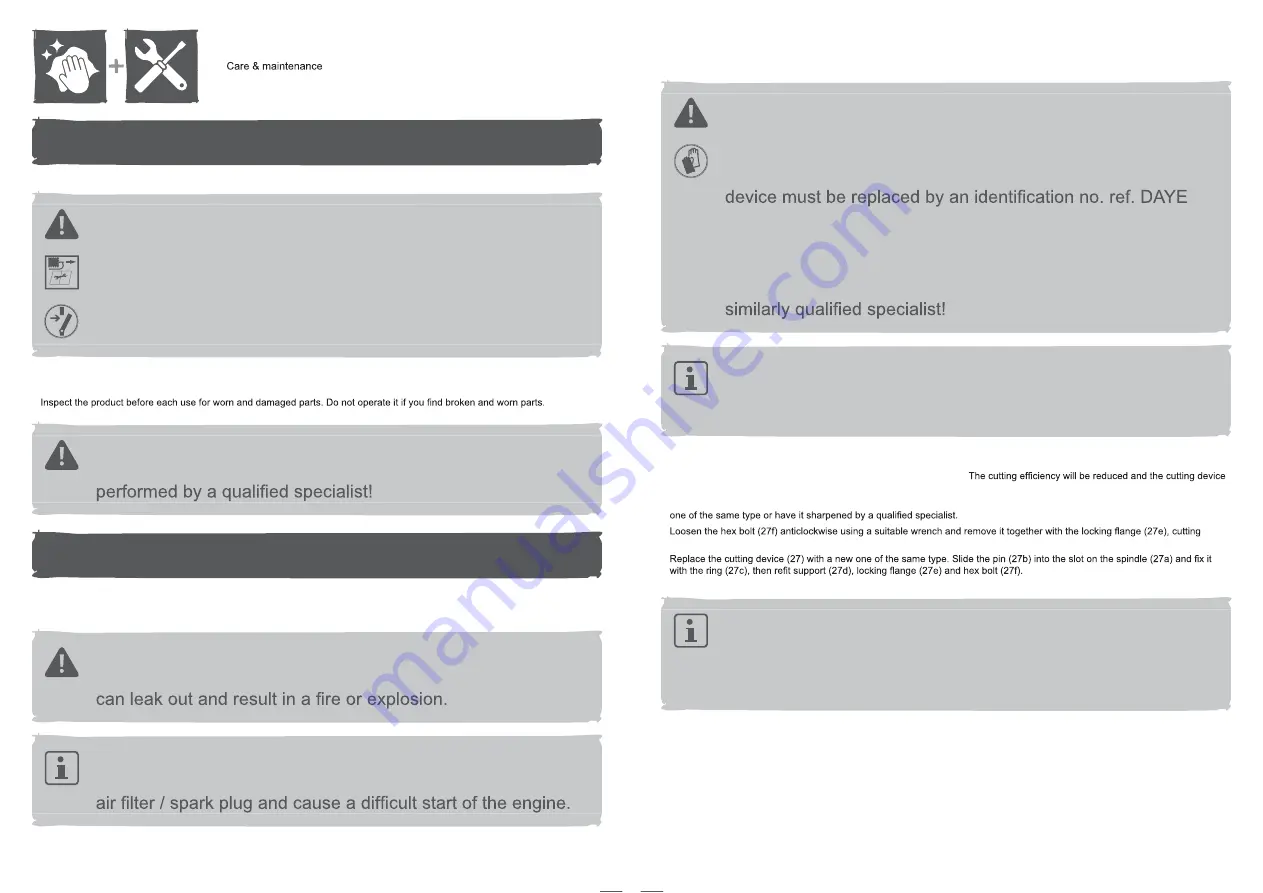
Care

WARNING! 

Always switch the product off, disconnect the 

spark plug connector / remove the battery pack and let the 
product cool down before performing inspection, maintenance 
and cleaning work! 

DO NOT touch a rotating blade.   

•  Keep the product clean. Remove debris from it after each use and before storage. 

•  Regular and proper cleaning will help ensure safe use and prolong the life of the product. 

• 

WARNING! 

Only perform repairs and maintenance work 

according to these instructions! All further works must be 

Product maintenance

Before and after each use, check the product and accessories (or attachments) for wear and damage. If required, exchange them 
for new ones as described in this instruction manual. Observe the technical requirements.

WARNING! 

It requires to tip the product when perform the 

maintenance, therefore the fuel tank must be empty or fuel 

NOTE: 

Always empty the fuel tank and keep the spark plug 

upside. Otherwise the fuel or engine oil will contaminate the 

37

Underbody and cutting device

WARNING! 

Wear protective gloves when working on the 

cutting device and close to it! Use proper tools to remove 
debris, e. g. a wooden stick! Never use your bare hands! 

Always use original spare parts for replacement. The cutting 

263001465. Do not attach any other type of cutting device! 

The replacement of the cutting device should be done by 
an experienced user! Rework or sharpening blades is not 
recommended unless it is done by a repair service or a 

NOTE: 

We strongly recommend jacking the product up when 

performing inspection and work on the cutting device. Avoid 
tilting the product in order to prevent fuel and oil leakages.   

•  Keep the underbody and cutting device (27) clean and free of debris. Remove clippings from the rear discharge chute (25). 

•  Check all nuts and bolts periodically for tightness before operation. After prolonged use, especially in sandy soil conditions, the 

cutting device will become worn and lose some of the original shape. 
should be replaced. 

•  Keep the cutting device (27) sharp to ensure a good cutting performance. Replace a worn or damaged cutting device with a new 

• 

device (27), support (27d), ring (27c) and pin (27b) (Fig. 33). 

• 

NOTE: 

Replace this cutting device after 50 hours mowing or 

2 years whichever is sooner regardless of condition. If the 
cutting device is cracked or damaged, you must immediately 
replace it with a new one. 

•  Lubricate the cutting device (27) after each use to prolong the life span of cutting device and product. Apply light machine oil along 

the edge of the cutting device.

Tighten the hex bolt clockwise with 40 Nm min, 

50 Nm max. to ensure safe operation of your product.

Содержание MLMP575SP46

Страница 1: ...nal instructions 3 Sheldon Square London W2 6PX United Kingdom Distributor B Q plc Chandlers Ford Hants SO53 3LE United Kingdom www diy com SFD Limited Trade House Mead Avenue Yeovil BA22 8RT United K...

Страница 2: ...on 4 Assembly 18 Use 26 36 x2 Unleaded Petrol SAE10W 30 Engine Oil 01 02 03 04 06 05 1 2 3 4 5 6 7 These instructions are for your safety Please read them thoroughly before use and retain for future r...

Страница 3: ...e the engine governor settings or overspeed the engine Do not alter or tamper with any sealed adjustments for the engine speed control Do not tamper or disable any lawnmower safety systems or features...

Страница 4: ...overheating Do not place the charger near any heat source electric shock or electrocution If an extension cord must be used ensure pins on plug of extension cord are the same number size and shape as...

Страница 5: ...am per kilowatt per hour mAh Milliampere hour kg h Kilogram per hour kW Kilowatt C Degree Celsius cm Cubic centimetre F Degree Fahrenheit min or min 1 Per minute dB A Decibel A rated mm Millimetre m s...

Страница 6: ...s thrown by the product could hit the user or other bystanders Always ensure that other people and pets remain at a safe distance from the product when it is in operation In general children must not...

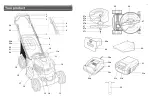
Страница 7: ...12 Your product 1 2 3 4 5 6 7 4 5 6 7 3 2 1 8 10 11a 9 24 22 21 20 23 20b 20a 12 11 13 14 15 16 17 18 19 13 27 26 27a 27b 27c 27d 27 27e 27f 25 28a 28 29 30a 31 31a 31b 31c 30b 30 30c 30d 32...

Страница 8: ...8 Oil tank cap 19 Lever for cutting height adjustment 20 Grass catcher a Handle b Hatch c Hook d Rod 15 NOTE Parts marked with are not shown in this overview Please refer to the respective section in...

Страница 9: ...per measures to protect yourself against vibration exposures Take the whole work process including times the product is running under no load or switched off into consideration Proper measures include...

Страница 10: ...nd electric cord 23 run on the upper side of the handle bars 4 7 Align the lower handle bar 7 with the handle supports 7a Make sure the mounting holes in the lower handle bar are aligned with those in...

Страница 11: ...onto the sliding slots 30b of the charger 30 all the way to the stop Fig 9 Connect the charger 30 to the power supply The charging status indicator RED 30d turns on Once charging is done this normally...

Страница 12: ...truction manual of the engine Service the engine with proper petrol and engine oil as instructed in the separate engine handbook 33 It is important to read and understand these instructions of the eng...

Страница 13: ...ever for manufacturing reasons it is possible that a small quantity may be in the engine Before operating this product it is essential to service life Non detergent or 2 cycle engine oils will damage...

Страница 14: ...essories for damage before each use Do not use the product if it is damaged or shows wear Always hold the product by its handle Keep the handle dry and and free from lubricant to ensure safe support E...

Страница 15: ...ts Fig 17 step 2 When you are ready to mow hold the handle 1 keep the brake bar 2 squeezed and then pull the drive bar 3 towards the handle 1 Fig 17 step 3 The product starts moving forward and begins...

Страница 16: ...ig 22 Fig 22 8a 31 07 Brake bar Pull the brake bar 2 towards the handle 1 and hold it in position when starting the engine Keep it squeezed during operation Fig 23 Release the brake bar 2 to stop the...

Страница 17: ...the rear discharge chute 25 make sure the side discharge attachment 29 and grass catcher Avoid mowing when the grass is wet from rain or dew Wet grass may form clumps which interfere with the mulchin...

Страница 18: ...ing Make sure that the lawn is clear of stones sticks wire or other objects that could damage the product or its engine Do not cut wet grass because it tends to stick to the underbody of the product p...

Страница 19: ...r replacement The cutting 263001465 Do not attach any other type of cutting device The replacement of the cutting device should be done by an experienced user Rework or sharpening blades is not recomm...

Страница 20: ...e parts are available at an authorised dealer or through our customer service Description Spark plug 14a XC92YC Blade 27 DAYE 263001465 Charger 30 IS12C Battery pack 31 IS12B Repair This product does...

Страница 21: ...Cutting height is incorrect 8 1 Replace with a new one 8 2 Only cut materials according to the capacity of the product 8 3 Adjust cutting height 9 Excessive vibration noise or exhaust 9 1 Cutting devi...

Страница 22: ...ectives The Machinery Directive 2006 42 EC EN ISO 5395 1 2013 A1 2018 EN ISO 5395 2 2013 A1 2016 A2 2017 The EMC Directive 2014 30 EU EN ISO 14982 2009 The Outdoor Noise Directive 2000 14 EC 2005 88 E...

Отзывы: