


EN
14
Getting
started...
MLM1334
by MacAllister
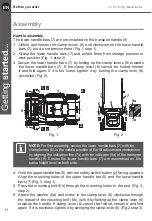
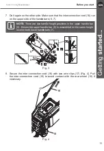
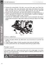
NOTE:
For first assembly, secure the lower handle bars (7) with the
clamp levers (6) in the middle position of the tilt adjustment mechanism
by aligning the indication line (7a) with the indicator (9a) of the transport
handle (9). Ensure the lower handle bars (7) are assembled on the
same height level on both side.
Handle assembly
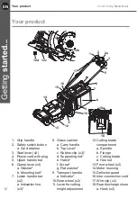
The lower handle bars (7) are pre-installed on the transport handle (9).
1. Unfold and loosen the clamp levers (6) anti-clockwise on the lower handle
bars (7), but do not remove them (Fig.1, step 1).
2. Grasp the lower handle bars (7) and unfold them from storage position to
work position (Fig. 1, step 2).
3. Secure the lower handle bars (7) by folding up the clamp levers (6) towards
the lower handle bars (7). If the clamp lever (6) cannot be folded, loosen
it and fold again. If it is too loose, tighten it by turning the clamp lever (6)
clockwise (Fig. 2).
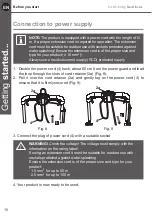
4. Hold the upper handle bar (5) with the safety switch button (2) facing upwards.
Align the mounting holes of the upper handle bar (5) and the lower handle
bars (7) (Fig. 3, step 1).
5. Pass the mounting bolt (6b) through the mounting holes to the end (Fig. 3,
step 2).
6. Attach the washer (6a) and screw in the clamp lever (6) clockwise through
the thread of the mounting bolt (6b), lock it by folding up the clamp lever (6)
towards the handle. If clamp lever (6) cannot be folded, loosen it and fold
again. If it is too loose, tighten it by swinging the clamp lever (6) (Fig.2,step 3).
Before you start
Assembly
6
6
7
7
9
1.
2.
1.
2.
Fig. 1
7
7
9
6
6
9a
7a
Fig. 2
Содержание MLM1334
Страница 37: ...EN 37 In more detail MLM1334 by MacAllister Declaration of conformity Declaration of conformity ...
Страница 38: ......
Страница 39: ......
Страница 40: ......


