R7I4DECT-1-PA8A
5-2-55, Minamitsumori, Nishinari-ku, Osaka 557-0063 JAPAN
Phone: +81(6)6659-8201 Fax: +81(6)6659-8510 E-mail: [email protected]
EM-7779-F Rev.1 P. 5 / 11
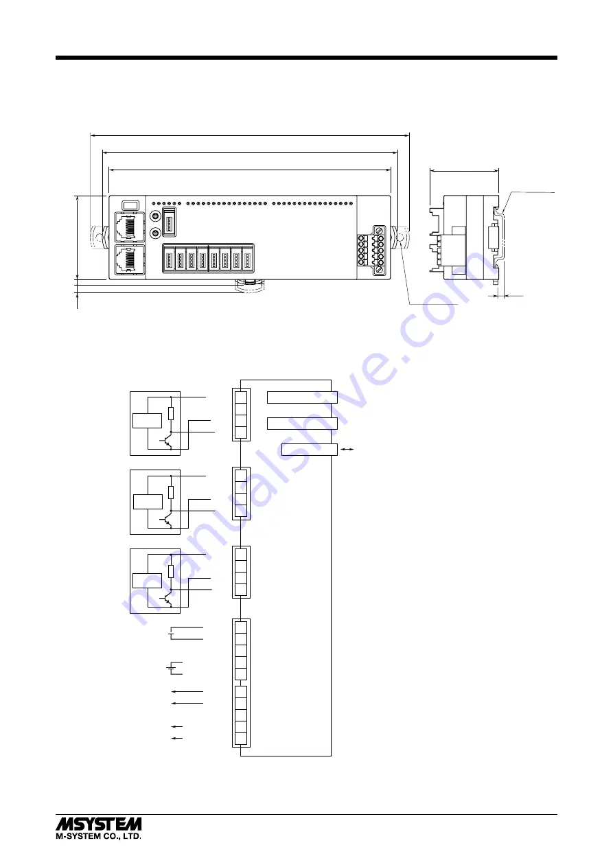
TERMINAL CONNECTIONS
Connect the unit as in the diagram below.
■
EXTERNAL DIMENSIONS unit: mm (inch)
41 (1.61)
165 (6.50)
172 (6.77)
186 (7.32)
DIN rail
(35mm wide)
50 (1.97)
3.5 (.14)
5
(.20)
4 (.16)
2-4.3 (.17) dia
4 (.16) deep
■
CONNECTION DIAGRAM
Note: In order to improve EMC performance, bond the FE terminal to ground.
Caution: FE terminal is NOT a protective conductor terminal.
SNSR.EXC+
SNSR.EXC–
FE
PWR–
PWR+
1
2
4
5
3
POWER SUPPLY (IN)
SENCOR EXCITATION (IN)
SNSR.EXC+
SNSR.EXC–
FE
PWR–
PWR+
1
2
4
5
3
POWER SUPPLY (OUT)
ENCOR EXCITATION (OUT)
PI0
GND
NC
GND
NC
+24V
PULSE INPUT PI0
1
2
4
3
PI7
+24V
1
2
4
3
PULSE INPUT PI7
GND
NC
RST
+24V
1
2
4
3
RESET INPUT
RJ-45 Modular Jack
RJ-45 Modular Jack EtherCAT (IN)
EtherCAT (OUT)
USB Connector
CONFIGURATION CONNECTOR
Detecting
Circuit
Detecting
Circuit
Detecting
Circuit
· ·
· ·
· ·
· ·
· ·


