73VR2102 / 73VR2104 / 73VR2106
73VR2108 / 73VR2110 / 73VR2112
– 18 –
■
CONNECTING THE POWER SUPPLY
• Please confirm rated voltage by spec label.
Rated Voltage
Operational Voltage Range
Power Consumption
AC Power
100 – 240V AC
85 – 264V AC
Approx. 25VA at 100V
Approx. 35VA at 240V
DC Power
24V DC
24V DC ±10%
Approx. 11W
• How to connect
(1) Open the power terminal cover at the rear.
(2) Loosen the three screws of power terminal.
(3) Wire power cable and protective grounding cable to the power terminal.
(4) Close the terminal cover.
■
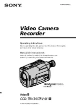
CONNECTING INPUT SIGNALS
The following explanation is an example with a thermocouple connected to Input 1, with
the Burnout detection type: Upscale/None.
• How to connect
(1) Turn off the power supply to the 73VR21x and open the input terminal cover.
(2) Connect (+) side of the thermocouple to 1B and (–) side to 1C.
(3) Close the input terminal cover.
☛
When connecting other signal types, see the 73VR21x User’s Manual Section 2.
FG
ALM
+
ALM
–
U
(+)
V
(–)
TRG
+
TRG
–
1A 1B 1C 3A 3B 3C 5A 5B 5C
2A 2B 2C 4A 4B 4C 6A 6B 6C
C
B
A
ext. wire
+
–
+
–