background image

A

C

D

X

ON

1  2   3  4

ON

(switch up)

O1

O2

O3

NO

NC

NO                 NC

OFF

(switch down)

O2

O2

O2

O1

O3

Page 10 of 16 


75.0036.02 LZR-FLATSCAN 3D SW 20210215

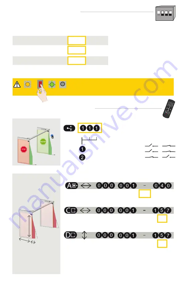
REMOTE CONTROL SETTINGS (OPTIONAL)

Width of the pinch zone

Width of the door zone

Height of all zones

DIMENSIONS OF ZONES

DIP  2    ENVIRONMENT         

After changing a DIP switch, the orange LED flashes. A LONG push on 

the push button confirms the settings. Afterwards, a number of green 

flashes (x) indicates the number of connected modules.

ORANGE

OFF

GREEN

DIP  4    PINCH  ZONE                 

Switch to CRITICAL when external disturbances 
are likely to cause unwanted detections (min. obj size, 
immunity, and uncovered zone are increased).

Switch to OFF when the pinch zone does not need 
to be secured or when objects can cause unwanted 
detections.

Always enter 3-digits when adjusting detection zone dimensions.
C and D: a teach-in overwrites these values automatically.
* The actual dimensions depend on the mounting height (40 in at 13 ft).  

In order to change these settings by remote control, adjust 

DIP switch 4 

to 

ON

.

standard

on

off

critical

in

001

-

15.75

40*

no field

In order to adapt these parameters by remote control, set the corresponding DIP switch to ON.

DIP 3  BACKGROUND               

Switch to OFF when there is no background (glass 
floor, pedi-mat, etc).

on

off

OUTPUT 

CONFIGURATION

(Normally open) 

 
(Normally closed)

Always enter 3 digits for output parameters:

• 1st digit refers to Output 1 (O1) = STOP
• 2nd digit refers to Output 2 (O2) = REOPEN
• 3rd digit refers to Output 3 (O3) = VIRTUAL PUSH BUTTON

NO POWER

NO DETECTION

DETECTION

DIP SWITCH SETTINGS (OPTIONAL)

in

in

001

001

-

-

157

157

no field

no field

Содержание FLATSCAN 3D SW

Страница 1: ...2 LZR FLATSCAN 3D SW 20210215 Page 1 of 16 EN SAFETY SENSOR FOR AUTOMATIC SWING DOORS User s Guide for software version SW 0100 and higher refer to tracking label on product Visit website for availabl...

Страница 2: ...t cover the laser window Avoid the presence of smoke and fog in the detection field Avoid condensation Avoid exposure to sudden and extreme temperature changes Keep the sensor permanently powered in e...

Страница 3: ...as the pinch zone To do so a sensor must be installed in the upper corner of the door leaf s 1 push button 2 DIP switch 3 lock screw 4 angle adjustment screw 5 primary secondary connector 6 main conne...

Страница 4: ...screws When mounting the base make sure the sensor will not interfere with door movement If the sensor isn t correctly positioned it could be damaged during the opening closing of the door Things to o...

Страница 5: ...e primary secondary cable through the hole and then position the cable in the notch of the base and ensure it is secure Secondary sensor sensor connected to the primary sensor by pass through cable Pa...

Страница 6: ...used by the flexible tube Pass the power cable through the flexible tube and connect the white plug to the white connector Create a loop with the wires of the power cable and pass them through the not...

Страница 7: ...can be NO or NC NO default See page 10 3 Knowing act door and control does not have secondary activation Use a BR3 X function 22 and LE21 4 O3 is only operational when the gray wires of the FLATSCAN 3...

Страница 8: ...s connected between the modules the detection field is free of snow buildups heavy rain snowfall fog or other objects or people the laser window protection is removed for FLATSCAN SW Primary FIELD WID...

Страница 9: ...he primary sensor to the activation on the door controller with the 10 wire cable provided 1 When the green LED flashes hold your hand in the desired position within C2 to learn the Virtual Push Butto...

Страница 10: ...to be secured or when objects can cause unwanted detections Always enter 3 digits when adjusting detection zone dimensions C and D a teach in overwrites these values automatically The actual dimensio...

Страница 11: ...on application and installation In order to change these settings by remote control ensure that DIP switch 2 is set to ON BACKGROUND ANTIMASKING This is a protective function that detects an unwanted...

Страница 12: ...ess code cycle the power During 1 minute you can access the sensor without introducing any access code field width 2 35 m To end an adjustment session always lock the sensor Enter the existing code x...

Страница 13: ...com sizer flatscan DETECTION FIELDS 4 in SERVICE MODE max 13 ft Service Mode deactivates all detection fields for 15 minutes and can be useful during an installation a mechanical learn of the door or...

Страница 14: ...elicate 3 Launch a new teach in closed door 4 Switch DIP 2 to off critical environment The red LED blinks quickly when trying to unlock the sensor The sensor is protected by a password Enter the right...

Страница 15: ...urn off DIP 3 deactivate background Something close to the sensor is masking part of the detection field 1 Ensure the laser window is not scratched If it is replace sensor 2 Remove all masking element...

Страница 16: ...cannot be held responsible for incorrect installations or incorrect adjustments of the sensor device therefore BEA Inc does not guarantee any use of the sensor device outside of its intended purpose B...

Отзывы: