vi
Table of Contents
MX6 PPC Reference Guide
E-EQ-MX6PCRG-C-ARC
Illustrations
Figure 1-1 Start Screen - Pocket PC 2002 ...........................................................................................................1
Figure 1-2 Start Screen - Windows Mobile .........................................................................................................1
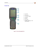
Figure 1-3 Front of 56-key MX6 PPC .................................................................................................................3
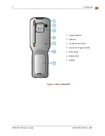
Figure 1-4 Back of MX6 PPC..............................................................................................................................4
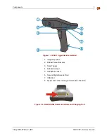
Figure 1-5 With Trigger Handle Installed............................................................................................................5
Figure 1-6 RS-232/USB Communications and Charging Port ............................................................................5
Figure 1-7 Imager Decode Zone ..........................................................................................................................7
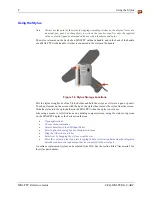
Figure 1-8 Stylus Storage Locations....................................................................................................................8
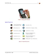
Figure 1-9 Tapping with the Stylus .....................................................................................................................9
Figure 1-10 System Tray Icons............................................................................................................................9
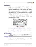
Figure 1-11 Soft Input Panel..............................................................................................................................10
Figure 2-1 AC/DC 12V External Power Supply................................................................................................17
Figure 2-2 Align the Touchscreen .....................................................................................................................18
Figure 2-3 Set the Date and Time ......................................................................................................................19
Figure 2-4 Set Backlight ....................................................................................................................................20
Figure 2-5 Audio Jack Location ........................................................................................................................24
Figure 2-6 Handstrap .........................................................................................................................................25
Figure 2-7 Scan and Decode LEDs....................................................................................................................27
Figure 2-8 Scan Beam........................................................................................................................................28
Figure 3-1 System Hardware .............................................................................................................................29
Figure 3-2 Secure Digital Memory Interface Card Location .............................................................................31
Figure 3-3 COM Ports .......................................................................................................................................32
Figure 3-4 MX6 PPC RS-232 Port ....................................................................................................................33
Figure 3-5 IR Port Location...............................................................................................................................34
Figure 3-6 Power Modes – On, Suspend and Off..............................................................................................37
Figure 3-7 The 35-key and 56-key Keypads......................................................................................................39
Figure 3-8 Modifier Keys ..................................................................................................................................41
Figure 3-9 MX6 Multicharger ...........................................................................................................................47
Figure 4-1 Inbox ................................................................................................................................................54
Figure 4-2 Start ActiveSync...............................................................................................................................61
Figure 4-3 WLAN Settings – Status Screen ......................................................................................................69
Figure 4-4 Ping Utility .......................................................................................................................................71
Figure 4-5 WLAN Settings – Config Screen.....................................................................................................72
Figure 4-6 WLAN Settings – Advanced Screen................................................................................................74
Figure 4-7 WLAN Settings – About Screen ......................................................................................................75
Figure 4-8 Add / Edit Network Profiles Display ...............................................................................................77
Figure 4-9 Delete a Profile.................................................................................................................................79
Figure 4-10 WLAN Status Icon.........................................................................................................................80
Figure 4-11 Align Screen...................................................................................................................................87


