background image

20 | 

P a g e


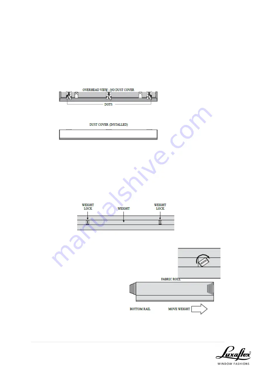
OPTIONAL DUST COVER INSTALLATION  

 
The dust cover is used to protect the top of the headrail from exposure to dust on 
face fit installations. To attach the dust cover, remove the backing from one side 
of the Velcro dots. Apply the dots to the installation brackets on each end of the 
shade and remove the remaining paper from the dots. Centre the dust cover 
over the top of the shade, above the previously placed dots and press down to 
secure. 


ADJUSTMENT  

 
Raise the window shading very slowly the first time and carefully watch how the 
fabric winds on the roll. It should wind evenly and not gather on either side. If the 
fabric roll becomes uneven or starts to rub against one end of the headrail, stop 
raising the shading immediately and adjust the balance weight on the bottom 
rail. 


To release the weight, insert a coin in 
the  right-side  weight  lock  and  turn  it 
clockwise.  You  can  then  release  the 
left-side  weight  lock,  again  turning  it 
clockwise.  Adjust  the  weight  by 
moving it in 25mm increments toward 
the side where the fabric is gathering. 
After making the adjustment, lock the 
weight  locks  in  position  by  turning 
them  counter-clockwise.  Lower  the 
window  shading  all  the  way  and 
again raise it slowly, watching how the 
fabric winds. If necessary, readjust the 
weight in 25mm increments, being careful not to over-adjust. 


Содержание Silhouette Shades

Страница 1: ...Silhouette Shades Product Manual...

Страница 2: ...fety One cord operates tilt lift PowerView Automation Easy to operate child safe low voltage easy to install no wiring options Choice of fabrics Colours that co ordinate with customers decor Choice of...

Страница 3: ...3 P a g e PRODUCT VIEW...

Страница 4: ...h translucent fabric diffuse light to provide soft filtered light When the vanes are tilted open the view is still visible ROOM DARKENING When room darkening fabric is selected the shades close to ach...

Страница 5: ...or effortless operation to raise and lower the shade Single cord length for improved aesthetics and child safety POWERVIEW AUTOMATED CONTROL Perfect for hard to reach windows Powered by battery wand o...

Страница 6: ...6 P a g e LIMITATIONS Limitations...

Страница 7: ...l measurements should be wood to wood or opening sizes Factory will make deductions FACTORY DEDUCTIONS Inside fitting Width 5mm Drop 5mm Outside fitting Width As per given measurement Drop 5mm ARCHITR...

Страница 8: ...d No 1 is through blind Blind No 2 is butting blind Measure to back corner and deduct 86mm State on order whether you have made the corner deduction or not The installation bracket does not protrude p...

Страница 9: ...es Determine where in the reveal the blind will sit 83mm required Measure at the front edge where the headrails meet record and write down butting There will be approximately 30mm gaps between fabrics...

Страница 10: ...Right Left Controls 26mm Left Right Controls 14mm Minimum Recess Without Back Cover 25mm Mount Depth With Back Cover 30mm Minimum Fabric Clearance 3mm Cord Loops White 300mm 600mm 1800mm 2100mm 2400mm...

Страница 11: ...11 P a g e HEADRAIL SIDE ELEVATION...

Страница 12: ...p 300mm Maximum Drop 3050mm 3050mm 2590mm 2840mm 2440mm Light Control Side Gaps Idle End 13mm 7mm Minimum Rear Fabric Clearance 3mm Minimum Recess Depth Oversize Headrail Depth 25mm 83mm Fully Recesse...

Страница 13: ...m Width DC Power Supply 310mm Maximum Width 2760mm 3040mm 3040mm 3040mm 3040mm Minimum Drop 300mm Maximum Drop 3040mm 2590mm 2840mm 2440mm 3040mm Light Control Side Gaps Idle End 13mm 7mm Minimum Rear...

Страница 14: ...position Refer to the PowerView Motorization Remote Control Guide on how to set a favourite position TOP DOWN BOTTOM UP DAY NIGHT OPERATION 1 Press CLOSE to lower the bottom rail closing the shade 2...

Страница 15: ...on with PowerView Hub PowerView Pebble Can house either Remote or Scene Controller Surface Wall Mount Can house either Remote or Scene Controller PowerView Hub Kit Includes PowerView Hub USB Power Sup...

Страница 16: ...ing ordered should include Installation brackets see chart 2 hold down brackets optional 2 screws for each bracket 20mm x 6 Panhead TOOLS REQUIRED Steel measuring tape Carpenter s level Power or batte...

Страница 17: ...he final location of the bracket centrelines is 100mm or more from the ends of the headrail the limit stops must be moved Reposition the limit stops so that their centrelines are 50mm from the ends of...

Страница 18: ...f the installation brackets on a flat vertical surface at least 20 mm high Two screws are used to attach each bracket Position the brackets on the centrelines you marked and then attach them with the...

Страница 19: ...of a bracket may be cut off This should be done before mounting the bracket INSTALL THE WINDOW SHADING With the front of the headrail facing you push the top edge of the headrail into the installatio...

Страница 20: ...roll It should wind evenly and not gather on either side If the fabric roll becomes uneven or starts to rub against one end of the headrail stop raising the shading immediately and adjust the balance...

Страница 21: ...each hold down bracket so it is at the bottom of the bracket The vanes may then be opened and closed while the bottom rail is connected to the brackets The bottom rail must be disconnected from the ho...

Страница 22: ...e hand spun sheer the Silhouette Shadings fabric is subject to slight variations The fabric will change as its position changes Minor wrinkles puckers or other variations can appear and are inherent t...

Страница 23: ...ection fabric covered headrail Lightly dust with a clean dry cloth TO THE CLEANER ULTRASONIC CLEANING Use a mild cleaning solution with a neutral PH Ensure water temperature does not exceed 48 C 120 F...

Отзывы: