Lunar DPX-IQ Скачать руководство пользователя страница 120

G-4

Orthopedic Hip

DPX-IQ Operator’s Manual

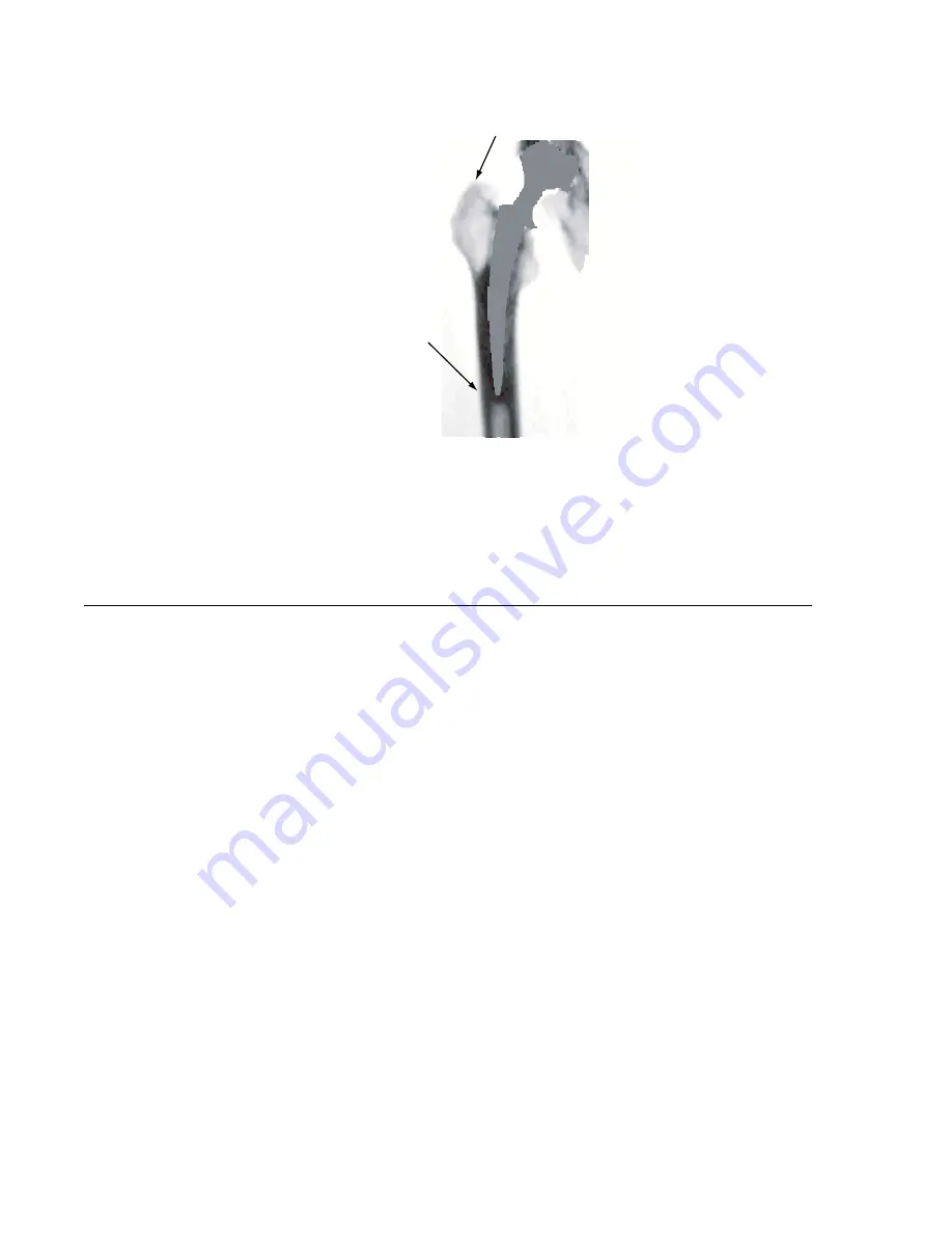
Figure G-3.  Orthopedic hip scan image

11. After the scan, remove the patient’s foot from the foot brace and help the patient off 

the scan table.

12. Select 

!

 to go back to the Orthopedic Hip Options screen.

G.2

Orthopedic Hip Image Analysis

NOTE: In most cases, the software will accurately analyze the scan image. 

However, unusual anatomy or incorrect patient positioning may 
require you to complete manual adjustments to the scan image, such 
as ROI or edgemarker positions.

The procedure that follows gives the basic steps necessary to complete an orthopedic 
hip image analysis. Refer to section G.3 for more information.

1.

Refer to section 2.4.1 to select a patient scan file for analysis.

2.

At the Bone Results screen, select 

$

. The Auto Analysis screen is shown. Select the 

type of analysis:

Select 

(

 for a Gruen Analysis or 

'

 for an Extended Gruen Analysis.

For a Standard Analysis, continue with step 3.

3.

Select 

)

. The Profiles screen is shown. Make sure the edge markers are correct.

4.

Select 

+

. The Auto Analysis screen is shown. Make sure the ROIs and the 

Reference Point positions are correct.

5.

Select 

!

. The Bone Results screen is shown (figure G-4).

6.

Select 

)

 to save changes.

Содержание DPX-IQ

Страница 1: ...rope N V avenue R Vandendriessche 18 9 1150 Brussels Belgium 32 2 7770910 32 2 7791039 Fax LUNAR GmbH Horbeller Strasse 33 D 50858 K ln Germany 49 2234 954590 49 2234 273153 Fax LUNAR France 1 avenue...

Страница 2: ...isassemble any Program or any part thereof or merge any part of any Program into another computer program 2 Rent sell sublicense assign or otherwise transfer the Programs to a third party In the event...

Страница 3: ...ity 1 thoroughly familiarize yourself with the patient s history and 2 install the scanner in an environment effectively shielded from other sources of external radiation Federal Law restricts this de...

Страница 4: ...mergency stop button to routinely abort a scan Using the DPX IQ Operator s Manual Use this manual to help you complete daily acquisition and analysis procedures Chapter 1 System Overview gives scanner...

Страница 5: ...X DPX alpha DPX L We hereby declare that the above described product conforms to the requirements of the European Council Directive 93 42 EEC Medical Devices Directive Annex II This declaration is bas...

Страница 6: ...vi DPX IQ Operator s Manual This page left blank intentionally...

Страница 7: ...1 10 1 2 9 Scattered Radiation 1 10 1 3 System Maintenance 1 13 1 3 1 Clean the Scan Table Environment 1 13 1 3 2 Archive Scan Files 1 13 1 3 3 Test the Emergency Stop Button 1 13 1 4 Preventive Maint...

Страница 8: ...Archive Scan Files 2 11 2 6 1 Procedure to Archive Patient Scan Files 2 11 Change Archive Destination and Directory 2 12 Chapter 3 Quality Assurance 3 1 Quality Assurance Tests 3 1 3 1 1 Complete a QA...

Страница 9: ...Space Markers A 6 Examine Labels A 6 Examine Intervertebral Space Markers A 6 A 3 2 Examine Baseline and Edge Markers A 7 The Line Profile A 7 Examine Baselines A 8 Examine Edge Markers A 9 A 3 3 Com...

Страница 10: ...easure the Forearm Length E 3 E 2 2 Record the Scan Length E 4 E 2 3 Position the Forearm Positioner E 4 Forearm Position E 5 E 3 Forearm Image Analysis E 5 E 4 Analysis Information E 8 E 4 1 Examine...

Страница 11: ...3 H 3 Functional Specifications H 3 H 3 1 General Specifications H 3 H 3 2 Maximum Scan Area Long x Transverse H 3 H 3 3 Programs H 4 H 4 Environmental Specifications H 4 H 5 Power Specifications H 5...

Страница 12: ...xii Table of Contents DPX IQ Operator s Manual...

Страница 13: ...Revised 1 99C Chapter 1 System Overview 1 1 Scan Table Assembly NOTE DO NOT attempt servicing the scan table assembly Please call the LUNAR Customer Support Department or your LUNAR distributor Figure...

Страница 14: ...er monitor The position switches status lights and emergency stop button are on the control panel figure 1 2 Figure 1 2 Scan arm control panel Position switches The position switches move the scan arm...

Страница 15: ...the laser It is not likely that you can receive more than 25 of the maximum permissible x ray dose from the DPX IQ scanner However some facilities choose to use personnel monitors Refer to your city...

Страница 16: ...between the scan arm and the scan table At the end of a Lateral Spine acquisition a pinch point can be made between the patient s legs and scan arm The scan arm makes a pinch point on both ends of the...

Страница 17: ...yearly scattered radiation dose for the operator is approximately 166 67 Gy per year This assumes an estimated 10 patients per day 2 scans per patient and average time of 2 minutes per scan and 50 wee...

Страница 18: ...3 00 12 x 12 270 810 77 1 2 x 1 2 Total Body Screening 76 0 15 54 x 150 290 44 0 1 4 8 x 19 2 Total Body Fast 76 0 15 54 x 150 580 87 0 2 4 8 x 9 6 Total Body Medium 76 0 15 54 x 150 1160 174 0 3 4 8...

Страница 19: ...rays are off and not being generated at the same time the X ray On light on the scan arm control panel is off When this symbol appears with a green background the scanner is ready to begin making X ra...

Страница 20: ...ssembly This label gives collimator assembly information It is located on the collimator and foot panel of the scanner p n 5531 Rev D For USA Complies with Radiation Performance Standards in 21 USCFR...

Страница 21: ...Emergency stop button again to reset the system 3 Select The system turns off the x ray and the scan arm moves to the HOME position The Options screen is shown NOTE If there is a hardware problem DO...

Страница 22: ...computer equipment and accessories connected to the scanner must comply with IEC 950 Safety of information technology equipment including electrical business equipment and must conform with IEC 801 5...

Страница 23: ...PX IQ scanner was run at 76 kV and 4 75 mA EMERGENCY POWER ON X RAY SHUTTER LASER Back Front Left Right DPX IQ R Detector 1 Gy hr Tube Head Foot end View Water 1 Gy hr Gy hr Gy hr Gy hr Gy hr Gy hr Gy...

Страница 24: ...canner was run at 76 kV and 0 75 mA DPX IQ scanner was run at 76 kV and 4 75 mA EMERGENCY POWER ON X RAY SHUTTER LASER Back Front Left Right DPX IQ R 91 4 cm 30 cm 50 8 cm 25 4 cm 30 5 cm 50 8 cm 30 c...

Страница 25: ...makes free space on your hard drive Refer to section 2 6 for more information 1 3 3 Test the Emergency Stop Button Test the Emergency Stop button once a month Refer to the procedure that follows 1 Sta...

Страница 26: ...ir the components and scan table Doing so voids all current warranty and service contracts 1 4 2 Daily Quality Assurance Procedure Complete system Quality Assurance procedures daily Make sure each QA...

Страница 27: ...ion in this manual the term select is the act of pressing a key to operate the program 2 1 1 Options Screen When you start the LUNAR program an options screen is shown figure 2 1 The options that foll...

Страница 28: ...lect Reference Population to access the reference databases necessary to compare BMD results Exit to leave the LUNAR program and go back to the Windows desktop Figure 2 1 Options screen 2 1 2 Common K...

Страница 29: ...e x ray beam such as clothing with zippers snaps buckles and buttons Require patients to wear a jogging suit to the exam or give them an examination gown when they arrive Radionuclides and Radiopaque...

Страница 30: ...tient position Step 4 Locate Scan Start Position You must use the laser light to locate the scan start position for the detector A correct scan start position makes sure the program accurately scans t...

Страница 31: ...lbs or 136 4 kg Select 0 after each record NOTE To record patient height use whole numbers and make sure decimals greater than 0 5 are rounded to the next highest number 5 Select or to record patient...

Страница 32: ...isition screen is shown Change the scan values and select to start the scan 4 Continue the acquisition procedure End the Scan To end a scan select then select two times During a femur scan make sure 2...

Страница 33: ...o change the image Type The options for Type are Bone and Soft Bone shows a skeletal image and Soft shows a soft tissue image Soft is an option for the Total Body scan type only Filtering Filtering sm...

Страница 34: ...g may require you to complete manual adjustments to the scan image such as ROI or edgemarker positions Refer to the applicable appendix for the scan type A thru G for procedures to analyze and if nece...

Страница 35: ...by the reference standard deviation SD A Z score of 2 means the patient is 2 SDs below the mean age matched value of the reference population Print a DICOM Report optional If you have purchased the D...

Страница 36: ...t Print select to print the Chronological Results screen for one patient 2 5 2 Graph and Print Patient Results 1 At the Chronological Results screen select the necessary scan type For example to graph...

Страница 37: ...an IQNET system 1 At the Options screen select The Database Utilities screen is shown 2 Select The Patient Directory screen shows scan files related to patient name 3 Select one of the options that f...

Страница 38: ...een you can change the drive destination and directory used to archive patient files 1 At the Database Utilities screen select 2 Move the cursor to the line that follows Archive Drive a ar_data 3 Type...

Страница 39: ...If a test fails two times call the LUNAR Customer Support Department or your LUNAR distributor DO NOT try to scan a patient until a successful QA test is complete 3 1 1 Complete a QA Test Use the stan...

Страница 40: ...o the correct results that follow The detector peak and the high keV and low keV peaks are no more than 50 units above or below the previous peak settings Each Functional Measurement has a spillover o...

Страница 41: ...lect to begin a QA procedure QUALITY ASSURANCE RESULTS X Ray Voltage kVp 76 0 Date 01 01 98 X Ray Current uA 150 0 System 0000 AMPLIFIER COUNTS COUNTS SETTING LOW keV HIGH keV 265 59862 1882 315 66818...

Страница 42: ...pical density range and size of a normal human spine The spine phantom figure 3 3 consists of vertebrae L1 through L4 Parts of vertebrae T12 and L5 are landmarks used by the DPX IQ program during anal...

Страница 43: ...er to the QA printout before this scan if you think the values are not correct Call LUNAR Customer Support or your Distributor 8 Select to go back to the AP Spine Acquisition screen 9 To scan the enca...

Страница 44: ...mate start position and the program turns on the laser light 14 Position the laser light figure 3 6 in the middle of L5 and in the center of the phantom Select to start the scan L5 L4 L3 L2 L1 T12 C A...

Страница 45: ...A for more information 1 From the AP Spine Options screen select The Patient Directory screen is shown Select the Spine Phantom Select 2 Select the phantom scan file for analysis Select The Mandatory...

Страница 46: ...ecision Over Time The Chronological Results screen lets you show graph and print results of spine phantom scans over time in chronological order 1 At the AP Spine Options screen select The Database Ut...

Страница 47: ...ify the date and time you want to print scan analysis or Quality Assurance results 4 1 1 Print Manager Options At the Options screen select to access the Print Manager screen The Print Manager screen...

Страница 48: ...which relates to the day of the week necessary to print the reports Select 0 NOTE If you select Daily the program prints reports each day at the selected time 5 Select then to go back to the Options s...

Страница 49: ...information which let you personalize analysis printouts a typical heading can show the name of your institution department or physician s name and address of your institution NOTE The Report Heading...

Страница 50: ...the type of report that is printed after scan analysis NOTE Option 4 sBMD is given only for AP Spine L2 L4 Total Femur and Femur Neck analysis Display Country Field Display Country Field lets you sho...

Страница 51: ...y Options 1 At the Report Heading screen select The Printout Display screen is shown 2 Highlight the value to be changed then select to turn the option ON or to turn the option OFF Each option is give...

Страница 52: ...e categorized as osteoporosis The footnote on the Results Report explains the T scores associated with each category The T score represents the patient s BMD result above or below a reference Young Ad...

Страница 53: ...because of smaller body sizes the values for U S women of Asian descent are similar to Caucasian values Age Regression Line Age Regression Line shows the line in the center of the Age Matched Regressi...

Страница 54: ...4 8 Default Settings DPX IQ Operator s Manual Figure 4 3 Analysis Results report 4 6d...

Страница 55: ...m shows the language on the Options screen 4 4 Select Reference Population The LUNAR program lets you compare patient bone mineral density BMD to a database of reference information You can choose fro...

Страница 56: ...4 10 Default Settings DPX IQ Operator s Manual This page left blank intentionally...

Страница 57: ...and select to go back to the AP Spine Acquisition screen 4 Select The scan arm moves to the HOME position 5 Help the patient lie on the scan table Select The scan arm and detector move to the approxi...

Страница 58: ...comfortable Figure A 1 Patient position 7 Position the laser light figure A 2 approximately 5 cm below the patient s navel and in the same longitudinal plane as the patient s midline Figure A 2 Laser...

Страница 59: ...to the scan image such as ROI or edgemarker positions The procedure that follows gives the basic steps necessary to complete an AP spine image analysis Refer to section A 3 for more information 1 Refe...

Страница 60: ...Results screen 6 Select The Analysis Results screen is shown Refer to figure A 4 which shows the two possible graphic styles you may see For AP spine analysis you can choose to display a WHO Fracture...

Страница 61: ...DPX IQ Operator s Manual AP Spine A 5 Figure A 5 AP Spine Analysis Report Figure A 6 AP Spine Ancillary Report...

Страница 62: ...e program labeled the necessary vertebrae To change labels complete the procedure that follows 1 At the Spaces Labels screen select The Select Labels window is shown 2 Use the arrow keys to select the...

Страница 63: ...ure A 8 Spine image and profile The Line Profile The Line Profile shows the information that follows figure A 9 Baseline The baseline is the horizontal line at the bottom of the profile The points bel...

Страница 64: ...correctly change the baseline ONLY if you are sure it is not correct Figure A 10 illustrates correct baseline position When you change the baseline the program automatically changes the edge markers...

Страница 65: ...nwanted soft tissue and is positioned on the baseline NOTE Calcification fat deposits and dense substances can cause unwanted soft tissue points to be shown on the Line Profile Figure A 11 Incorrect E...

Страница 66: ...t analysis Complete one of the steps that follow Select to let the software position the ROIs Select to not change the ROIs To remove or add ROIs select option or NOTE If you select the Bone Results s...

Страница 67: ...tor s Manual AP Spine A 11 7 Select The Analysis Results screen is shown 8 Select to save changes 9 Select and record the number of Analysis Results and or Ancillary reports necessary Select to print...

Страница 68: ...A 12 AP Spine DPX IQ Operator s Manual This page left blank intentionally...

Страница 69: ...2 for a left femur or 3 for a DualFemur scan 4 Select The Mode window is shown Refer to table B 1 to make sure the scan mode you select is correct for scan region thickness Highlight the applicable m...

Страница 70: ...h below the horizontal line on the scan pad Figure B 1 Patient position 8 The DPX IQ unit includes one of the two foot braces shown in figures B 2 and B 3 Follow the instructions for your model s brac...

Страница 71: ...le Rotate the ENTIRE leg until the foot is positioned at an angle against the foot brace 10 Select The scan arm and detector move to the approximate starting position and the program turns on the lase...

Страница 72: ...eater trochanter A message is shown which asks you if you want to continue the scan on the same femur If it appears that less than 25 lines of the scan are acquired above the greater trochanter select...

Страница 73: ...t tissue of leg Femur If necessary use two rice bags to get 18 75 cm of tissue equivalent material for a 3000 A scan The top rice bag is tight against the leg to prevent air gaps Let the patient hold...

Страница 74: ...rogram is acquiring the left or right femur Refer to section 2 3 5 for more information Abort between left and right femur scans You can select to abort the scan while the scan arm and detector are mo...

Страница 75: ...Trochanteric ROIs Refer to section B 4 2 for a description of these ROIs 5 Select The Bone Results screen is shown 6 Use the arrow keys to highlight the region to be shown on the Analysis Results scr...

Страница 76: ...B 8 Femur DPX IQ Operator s Manual Figure B 8 Femur Analysis Report Figure B 9 Femur Ancillary Report...

Страница 77: ...e scan was acquired incorrectly because of a bad starting location aborting too soon etc If the Bone Results Screen shows one of these messages refer to the procedure in section B 1 to complete the sc...

Страница 78: ...Neck ROI position Position the Neck ROI Complete the procedure that follows only if the program did not position the Neck ROI correctly 1 Select from the Bone Results screen 2 Select to move to expan...

Страница 79: ...DPX IQ Operator s Manual Femur B 11 Figure B 12 Position Neck ROI...

Страница 80: ...B 12 Femur DPX IQ Operator s Manual This page left blank intentionally...

Страница 81: ...in the scan region Patients more than 30 cm thick can not be scanned by the detector 3 Examine the other scan values and select 1 to go back to the Lateral Spine Acquisition screen 4 Select The scan...

Страница 82: ...e positioner and below the knees Make sure the patient s back is flat against the positioner and adjust the strap so the patient does not roll forward during the scan Position a foam wedge between the...

Страница 83: ...c crest If the detector position is not correct select to stop the scan Refer to section 2 3 5 Figure C 3 Correct lateral spine scan image 11 Continue the scan past the top of L2 Select to stop the sc...

Страница 84: ...d of the keyhole slots Figure C 4 Lateral positioner C 3 Lateral Spine Image Analysis NOTE In most cases the software will accurately analyze the scan image However unusual anatomy or incorrect patien...

Страница 85: ...ey are wrong 4 Select The Auto Analysis screen is shown Make sure the ROI positions are correct 5 Select The Bone Results screen is shown 6 Use the arrow keys to highlight the region to be shown on th...

Страница 86: ...C 6 Lateral Spine DPX IQ Operator s Manual Figure C 6 Lateral Spine Analysis Report Figure C 7 Lateral Spine Ancillary Report...

Страница 87: ...gram the Body ROI for L2 is labeled B2 L3 is labeled B3 and L4 is labeled B4 Middle ROI M The Middle ROI contains the middle part of the Body ROI The program supplies results for the middle part of th...

Страница 88: ...e they are between the vertebral bodies and located at the lowest point of bone density as shown on the histogram If a space marker is not correct use the arrow keys to select the marker and select Re...

Страница 89: ...s At the Auto Analysis screen select to verify profiles The Profiles screen shows the edge markers on the scan image figure C 11 Make sure that each profile is positioned along the edges of the verteb...

Страница 90: ...n of each ROI figure C 12 The ROI contains only bone The top and bottom edges of the ROI are in the center of the vertebral endplates The endplates are the light grey regions at the top and bottom of...

Страница 91: ...ion Refer to section D 2 for more information NOTE Make sure the patient removes all attenuation materials before you start the acquisition procedure 1 Refer to section 2 3 3 to add or select a patien...

Страница 92: ...ith palms against the scan table Figure D 1 Patient position 6 Select to start the scan The scan arm and detector move to the start position 7 Make sure the patient s head and feet are shown in the sc...

Страница 93: ...ith step 5 3 Select Use the options shown on the screen to change cut positions 4 Select The Bone Results Screen is shown 5 Use the arrow keys to highlight the region to be shown on the Analysis Resul...

Страница 94: ...the bottom of the Analysis Results screen call LUNAR Customer Support 7 Select to save changes 8 Select and record the necessary number of Analysis Results and or Ancillary reports figures D 4 D 5 an...

Страница 95: ...DPX IQ Operator s Manual Total Body D 5 Figure D 5 Total Body Analysis Report page 2 Figure D 6 Total Body Ancillary Report 3 6y...

Страница 96: ...show tissue quantitation results in the Body Composition section of the Ancillary results printout The tissue information combines fat and lean soft tissue Other tissue data in the report combines sof...

Страница 97: ...ow the chin Ribs There is a left and right rib cut shown on the scan image Position each cut as close to the spine as possible Do not include the spine in the rib region Arms There is a left and right...

Страница 98: ...esults for patients who weigh less than 75 kg Extended Research Analysis is recommended for patients who weigh more than 75 kg It is necessary to carefully position cuts for Extended Research Analysis...

Страница 99: ...processes information from the current cut positions and the Bone Results screen is shown If specific anatomical sites select and refer to section D 3 1 to position the cuts When finished select The p...

Страница 100: ...D 10 Total Body DPX IQ Operator s Manual This page left blank intentionally...

Страница 101: ...Verify Values window is shown 3 Record or examine the following information Forearm Length the length of the forearm to be scanned Patient Side the arm to be scanned left or right LUNAR recommends the...

Страница 102: ...1 Forearm position 9 Select The scan arm and detector move to the approximate start position and the program turns on the laser light 10 Position the laser light figure E 2 in the center of the patie...

Страница 103: ...r the scan stops select to continue the scan for 15 20 more lines Select 13 After the scan remove the patient s arm from the positioner Select to go back to the Forearm Options screen Figure E 3 Corre...

Страница 104: ...ngth Shaft scans the 33 shaft site Distal scans the distal end of the forearm and includes the Ultradistal site the 5 mm site and the 10 site Manual lets you record the necessary scan length Figure E...

Страница 105: ...ses the software will accurately analyze the scan image However unusual anatomy or incorrect patient positioning may require you to complete manual adjustments to the scan image such as ROI or edgemar...

Страница 106: ...s forearm and select If no continue with step 6 6 Make sure the Reference Point and ROI positions are correct If changes are necessary use the options shown on the screen to position the reference po...

Страница 107: ...DPX IQ Operator s Manual Forearm E 7 Figure E 9 Forearm Analysis Report Figure E 10 Forearm Ancillary Report...

Страница 108: ...e Region Labels To change the region labels select The Select Labels window is shown and gives the label combinations Each line contains a combination of the Region labels in the order shown on the sc...

Страница 109: ...baseline down Please refer to section A 3 2 for more information on baselines Examine Edge Markers Make sure the edge markers are positioned above the baseline to include only high density points Refe...

Страница 110: ...he radius and ulna meet as you move up the forearm to the wrist Figure E 13 Reference point and ROI position E 4 4 Examine ROI Heights The height of each ROI is shown on the right side of the Auto Ana...

Страница 111: ...positioned on the scan image where the ulna and radius are 5 mm apart figure E 15 this distance is given on the right side of the Auto Analysis screen 10 ROI The recommended height of the 10 ROI is 1...

Страница 112: ...E 12 Forearm DPX IQ Operator s Manual Total ROI The Total ROI contains the 33 ROI in figure E 16 the Ultradistal ROI and the area between them Figure E 16 Total ROI...

Страница 113: ...ide record the hand to be scanned left or right Mode The Mode window shows the 150 A detail mode Select to set the mode Scan Width select Manual for scan width Measure the width of the hand at its wid...

Страница 114: ...ight figure F 2 in the center of the wrist immediately distal to the ulna styloid process Figure F 2 Laser light position 9 Select to start the scan Monitor the first few lines to make sure the detect...

Страница 115: ...sis 1 Refer to section 2 4 1 to select a scan file for analysis 2 At the Bone Results screen select The Auto Analysis screen is shown 3 Select The Analysis Results screen is shown figure F 4 4 Select...

Страница 116: ...omments 1 See appendix on precision and accuracy Statistically 68 of repeat scans will fall within 1 SD 0 02 g cm2 BMD 1 7 Young Adult 2 Age Matched 3 Region g cm2 T Z TOTAL 0 422 Reference Data Not A...

Страница 117: ...ecord or examine the information that follows Porous Length Record the length of the porous coating If you do not know the porous length use the default value of 0 Implant Length Record the length of...

Страница 118: ...G 1 Knee positioner 8 Secure the foot of the leg to be scanned to the straight vertical side of the foot brace Make sure the patient s toes point up figure G 2 Refer to the information that follows t...

Страница 119: ...inue the scan until at least 5 lines show above the top of the greater trochanter NOTE If white lines show on the edges of the scan image there is not enough soft tissue around the scan region There m...

Страница 120: ...r positions The procedure that follows gives the basic steps necessary to complete an orthopedic hip image analysis Refer to section G 3 for more information 1 Refer to section 2 4 1 to select a patie...

Страница 121: ...Orthopedic Hip G 5 7 Select and record the necessary number of Analysis Results and or Ancillary reports figures G 5 and G 6 Select to print the reports Figure G 4 Bone Results screen Figure G 5 Ortho...

Страница 122: ...lect from the Auto Analysis screen to examine orthopedic hip edge markers the Profiles screen shows the scan image and Line Profile figure G 7 The Line Profile shows areas of the analysis region the p...

Страница 123: ...Figure G 7 Line Profile Examine Edge Markers Refer to the information that follows to make sure the edge marker positions are correct figure G 8 Pelvis Edge If the pelvis is shown on the scan image th...

Страница 124: ...diately next to the lesser trochanter figure G 9 Make sure the horizontal line of the Reference Point is in the center of the lesser trochanter and is parallel to the femoral shaft In addition the ver...

Страница 125: ...is ROIs figure G 10 ROI C is positioned by the program so its bottom edge is at the top of the lesser trochanter ROI D is immediately below ROI C The bottom edge of ROI C and the top edge of ROI D tou...

Страница 126: ...settings ROIs 2 and 6 are immediately above ROIs 3 and 5 There is no space between the bottom of ROI 2 and the top of ROI 3 In addition there is no space between the bottom of ROI 6 and the top of RO...

Страница 127: ...ning ROIs contain bone not affected by the porous coating After the boundaries are set the program divides the implant length equally between ROIs 2 and 6 and ROIs 3 and 5 The program positions ROI 4...

Страница 128: ...ample if you select an Offset value of 4 mm the program shows a set of edge markers 4 mm from the implant 1 At the Profiles screen select The number following Offset below the line profile is highligh...

Страница 129: ...tudinal Histogram figure G 14 shows the density of bone next to the implant Use this histogram to monitor bone remodeling along the entire length of the implant The program calculates BMD values for t...

Страница 130: ...G 14 Orthopedic Hip DPX IQ Operator s Manual Figure G 15 Transverse Histogram screen...

Страница 131: ...Specifications H 4 H 5 Power Specifications H 5 H 6 X ray Generator Specifications H 5 H 7 Compatible Components H 10 Revised 1 99C Appendix H Specifications H 1 Space Requirements Room dimensions mu...

Страница 132: ...mponent specifications H 2 1 Printer Your system may include one of the printers that follow For your printer s specifications refer to product literature HP LaserJet 6L 17 5 H x 8 2 W x 15 3 D 44 3 c...

Страница 133: ...eneral Specifications Focal spot to image receptor distance is 58 4 cm Attenuation equivalence of patient support table is 0 7 mm AI H 3 2 Maximum Scan Area Long x Transverse NOTE The maximum scan len...

Страница 134: ...a around the scan table Make sure there is a minimum clearance of 12 30 5 cm at the head and foot ends of the scan table at least 6 15 2 cm for the arm side and 18 45 7 cm for the operator side Ambien...

Страница 135: ...label on your scanner to determine which power specifications apply to your scanner Bertan Spellman 100 Range 90 110 VAC 50 60 Hz 10A P N 0311 and 0312 115 Range 103 127 VAC 50 60 Hz 10A 230 240 Range...

Страница 136: ...2 2 Continuous kV mA for maximum electric output power 76 kV 4 mA IEC 601 2 7 6 8 2 3 Intermittent kV mA for maximum electric output power 76 kV 5 mA IEC 601 2 7 6 8 2 3 Nominal electric power 0 4 kW...

Страница 137: ...al anode input power 361 Watts for an equivalent Anode input power of 361 W IEC 613 1989 Maximum anode heat content 6000 Joules IEC 613 1989 Anode heating and cooling curves Refer to figure H 2 IEC 61...

Страница 138: ...9 Nominal X ray tube voltage 76 kV Anode to Cathode 38 kV Anode to Earth 38 kV Cathode to Earth IEC 613 1989 Single load rating 361 W 4 75 mA 76 kV for up to 4 min 59 sec IEC 613 1989 Serial load rati...

Страница 139: ...H 6 4 Laser Specifications Table H 4 gives the specifications for the LUNAR laser Table H 4 Laser specifications Output Power 1mW Wavelength 670nm Frequency Drift 0 25nm C Laser Structure Gain Guided...

Страница 140: ...e contact LUNAR for more information For customers located internationally make sure the computer is certified to local requirements such as IEC 950 The computer must meet the requirements that follow...

Страница 141: ...3 2GB 32MB 233MHz w Windows 95 5579 Controller DPX IQ ACER America2 Computer Models 2021 2GB 16MB 166MHz 4761 2181 6 4GB 32MB 233MHz 5524 2341 8MB RAM 16 MB RAM 1 6GB 32MB 133MHz black 4115 4013 4491...

Страница 142: ...TV40P200X2112 0311 0312 Bertan6 Models 2411AP 2411AN 0312 0311 Tube Head Assembly LUNAR X Ray Tube Head Assembly 2288 1 Dell Computer Corporation Austin TX 2 ACER America Corporation San Jose CA 3 CIT...

Страница 143: ...s In the past reference values obtained with a different instrument LUNAR DP3 have been shown to be virtually identical in different white populations US Australia UK Spain Brazil Argentina 1 6 Variat...

Страница 144: ...I 3 list the mean BMD values used as DPX s AP spine reference data BMD values are presented in grams per centimeter squared g cm2 in ten year intervals The regions of interest are AP spine L2 L4 and l...

Страница 145: ...entheses 32 36 49 Age n Neck Ward s Trochanter Total 0 12 0 13 0 11 0 12 20 29 739 0 998 0 945 0 796 1 007 30 39 1067 0 973 0 888 0 782 0 998 40 49 1746 0 946 0 839 0 782 0 979 50 59 1799 0 881 0 753...

Страница 146: ...uivalent BMD52 Table I 6 lists the mean BMD used in LUNAR s total body reference data for females Table I 7 lists the mean BMD used in LUNAR s total body reference data for males BMD values are given...

Страница 147: ...7 Mean male BMD values for total body sites SD in g cm2 for each site is listed below site name in parenthesis 32 Age n Total Body Arms Legs Trunk Pelvis Spine 0 08 0 08 0 09 0 07 0 10 0 14 20 29 35...

Страница 148: ...0 984 1 345 0 986 1 204 1 146 40 49 83 1 210 0 995 1 339 0 990 1 196 1 166 50 59 86 1 232 1 000 1 351 1 001 1 196 1 179 60 69 236 1 203 0 977 1 332 0 996 1 164 1 203 70 79 151 1 177 0 937 1 306 0 974...

Страница 149: ...0 139 45 65 665 Ap Spine 1 71 0 0113 X Age 0 32 0 174 65 166 Ap Spine 1 16 0 0026 X Age 0 20 0 170 20 45 171 Lateral Spine 0 895 0 0047 X Age 0 25 0 118 45 65 125 Lateral Spine 1 190 0 0104 X Age 0 46...

Страница 150: ...25 and 100 kg I 4 1 Young Adult The Young Adult value compares a patient s BMD with the expected peak bone mass for a subject of the same sex and nationality The Young Adult age ranges for each scan s...

Страница 151: ...eacock M Slemenda C Johnston CC Weaver CM 1995 Peak bone mass in young women J Bone Miner Res 10 711 715 8 Bell NH Gordon L Stevens J Shary JR 1995 Demonstration that bone mineral density of the lumba...

Страница 152: ...determinants of peak bone mass and subsequent rates of bone loss In Osteoporosis I Christiansen C Arnaud CD Nordin BEC Parfitt AM Peck WA Riggs BL eds Proceedings of the Copenhagen International Symp...

Страница 153: ...spinal bone mineral density measured laterally a normal range for UK women Br J Radiol 67 157 161 36 Truscott JG Simpson D Fordham JN Compilation of national bone densitometry reference data in Ring E...

Страница 154: ...in women a longitudinal study over 15 years Calcif Tissue Int 49 90 94 48 Kr ger H Laitinen K 1992 Bone mineral density measured by dual energy x ray absorptiometry in normal men Eur J Clin Nutr 22 45...

Страница 155: ...g a spine or femur The DPX has shown a better precision than Gd153 based DPA about 01 g cm2 error on spine and femur phantoms Refer to tables J 1 and J 2 Measurements with the DPX system were repeated...

Страница 156: ...0 015 Table J 2 Short term 5 days precision of DPX for regions of total body scans Intrascanner n 34 and interscanner n 37 results for single skeletons in vitro and results for young subjects in vivo...

Страница 157: ...o intercept Accuracy for vertebral area was further validated by comparing the measured areas of three vertebral bodies L2 L4 in nine encapsulated spine phantoms using the DPX Figure J 1 Actual vs mea...

Страница 158: ...DP4 scanner in 11 young subjects The correlation between results was high r 0 96 SEE 0 02 g cm2 The regression line was congruent with the identity line figure J 3 Figure J 3 Comparison of DPA and DE...

Страница 159: ...valent to 25 cm patient thickness Corrections for scatter and hardening reduce this small thickness dependence at higher thicknesses figure J 5 Figure J 5 Effect of tissue thickness on results J 3 Ref...

Страница 160: ...J 6 Precision and Accuracy DPX IQ Operator s Manual This page left blank intentionally...

Страница 161: ...ay line profile 4 4 Femur B 6 Forearm E 5 Hand F 3 Lateral Spine C 4 Orthopedic Hip G 4 Results 2 8 Scan image 2 8 Total Body D 3 AP Spine Acquisition A 1 Analysis A 3 Baselines A 8 Body ROI A 10 Edge...

Страница 162: ...itor scan B 5 Neck ROI position B 9 Rice bags B 5 Scan modes B 1 Filtering 2 7 Forearm 10 ROI E 11 33 ROI E 10 5mm ROI E 11 Acquisition E 1 Analysis E 5 Baseline E 9 Bone labels E 8 Edge markers E 9 F...

Страница 163: ...ormation Database mini menus 4 4 Display country field 4 4 Options screen 2 1 Orthopedic Hip Acquisition G 1 Analysis G 4 Edge markers G 7 Extened Gruen analysis G 11 Gruen analysis G 11 Gruen Analysi...

Страница 164: ...1 4 Operator 1 3 Patient 1 4 Pregnancy restrictions 2 3 Radiation 1 5 Symbols 1 6 System 1 3 Scaling factor 2 7 Scan image Adjust 2 7 Analyze 2 8 Scan modes 1 5 Scan table 1 1 Components 1 1 Control p...

Страница 165: ...DPX IQ Operator s Manual Index 5 X X ray generator H 5 X ray tube Lunar 2288 H 7 H 8 Lunar 8022 H 7 Y Young Adult Results defined 2 9 Young adult BMD comparison I 8 Display on printout 4 5...

Страница 166: ...This page left blank intentionally...

Отзывы: