


ODiSI 6
ODiSI 6
User’s Guide
Page 74
7
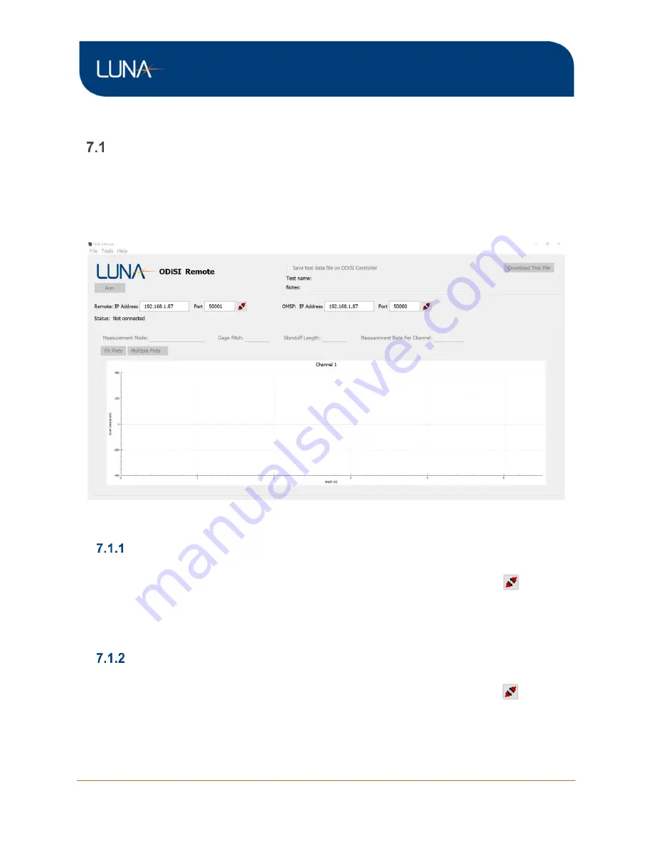
ODiSI Remote Operation
ODiSI Remote Application
The ODiSI Remote application provides the ability to Arm, Start, Stop, and Disarm the ODiSI
controller software from a remote PC. When the ODiSI controller software is making
measurements, the remote software will display the measurement data in real time. The ODiSI
instrument and controller must be running in order for the ODiSI Remote application to
connect successfully to the ODiSI controller.
Figure 7-1: ODiSI Remote application window
Remotely Control an ODiSI
Configure the Remote Software with the same IP address and port displayed in the main
ODiSI
control software’s Streaming Properties tab. Click the plug head button
, which will
change from red to green upon successful connection.
The ODiSI Remote application provides limited remote control functionality. The user can
Arm/Disarm, Start/Stop, and enable/disable test data file logging on the ODiSI controller.
Stream in ODiSI Measurement Data
Configure the Remote Software with the same IP address and port displayed in the ODiSI
main control software’s Streaming Properties tab. Click the plug head button
, which will
change from red to green upon successful connection.
Measurement data as defined by Gages and Segments will be streamed into the ODiSI
Remote application and can be displayed on a Sensor Plot. Within the Sensor Plot, Gages
will be displayed as circle markers while Segments will be displayed as a line plot.


