13
luminancebrands.com
Please contact 1-800-777-4440 for further assistance
ETL Model No.: CF590
6. Optional Installation of No-Light Plate Assembly
NOTE: To use the No-Light Plate Assembly, the
Light Kit Assembly MUST NOT Be Installed, or Light
Kit Assembly MUST Be Removed.
6.1
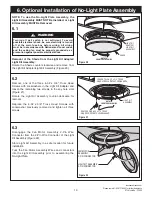
Removal of the Shade from the Light Kit Adapter/
Light Kit Assembly:
Rotate the Shade counter-clockwise and remove from
the Light Kit Adapter/Light Kit Assembly (Figure 20).
H
LIGHT KIT
ADAPTER/
LIGHT KIT
ASSEMBLY
SHADE
ROTATE
COUNTER-CLOCKWISE
Figure 20
H
LIGHT KIT
ASSEMBLY
REMOVE ONE 6-32 x 3/8" TRUSS
HEAD SCREW WITH LOCKWASHER
ROTATE
COUNTER-CLOCKWISE
LOOSEN TWO 6-32 x 3/8" TRUSS
HEAD SCREWS WITH LOCKWASHERS
Figure 21
6.2
Remove one of the three 6-32 x 3/8” Truss Head
Screws with Lockwashers in the Light Kit Adapter and
loosen the remaining two screws in the key hole slots
(Figure 21).
Rotate the Light Kit Assembly counter-clockwise for
removal.
Replace the 6-32 x 3/8” Truss Head Screws with
Lockwasher previously removed and tighten all three
screws.
LIGHT KIT ASSEMBLY
2-PIN CONNECTOR
FAN MOTOR
ASSEMBLY
2-PIN CONNECTOR
Figure 22
6.3
Disengage the Fan Motor Assembly 2-Pin Wire
Connector from the 2-Pin Wire Connector of the Light
Kit Assembly (Figure 22).
Store Light Kit Assembly in a safe location for future
installation.
Tuck the Fan Motor Assembly Wires and connectors
into the Light Kit Assembly prior to assembling the
No-Light Plate.
Turning off wall switch is not sufficient. To avoid
possible electrical shock, be sure electricity is turned
off at the main fuse box before wiring. All wiring
must be in accordance with National and Local codes
and the ceiling fan must be properly grounded as a
precaution against possible electrical shock.
WARNING
!
Содержание CF590GRT00
Страница 102: ...102 Mod le ETL N CF590 Notes...

