TECNICAL MANUAL
7. 1 i n s t a l l a t i o n
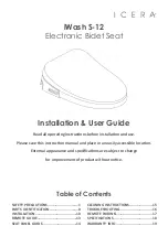
Electrical and Floor
Plumbing Fixing
65
36
12
36
12
17
36
26
36
62
Shampoo unit structure - floor fixing instructions
36cm for ‘Service Centre’ cabinet
48cm for ‘Wall System’ cabinet
B
Variable measurement - No less than 50 cm
C
Work space
A
Hot and cold water inlet tube
D
Water outlet tube
E
Measurement from wall
F
Water Inlet 3/8” - Outlet ø40
G
Electric point - 100/220-240 V
H
Electrical and Wall
Plumbing Fixing
36
50
72
16
122
46
88
38
36
50
20
30
A
B
C
E
D
E
D
H
35
62
36
50
83
133
5
18
62
36
50
95
A
B
C
G
G
F
H
H
52
Installation
TECNICAL MANUAL
7. 2 m a i n t e n a n c e
1.
Remove the plug from the electrical socket
2.
With your hands remove the backrest
3.
Remove the plug from the power supply
4.
Unscrew the 4 crankcase knobs
5.
Remove the casing and lubricate the PVC
back cloth of the massage
EVERY SIX MONTHS INSPECT THE FITTINGS OF THE WATER SYSTEM AND THE PVC CLOTH WHERE THE MASSAGE WHEELS
FLOW AND, DEPENDING ON THE FREQUENCY OF USE, LUBRICATE IT WITH SYNTHETIC RUBBER SUCH AS TOPAS NB 52.
53
Maintenance
EN
EN