LSC1264 Owner's Manual
page 3
5. install winch
6. install wheel
4. cradles
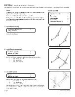
Install a cradle, cradle tie bars, and the pulley bar on top of the front H-unit.
Install the second cradle and the tie bars on the rear H-unit using:
4 - 1/2" x 3 1/2" hex bolts
4 - 1/2" nylon lock nuts
Attach the cradle spreader tubes between the front and rear H-units and
attach the cradle end caps using:
8 - 5/16" x 6 1/2" hex bolts
4 - angle caps
8 - 5/16" flat washers
8 - 5/16" nylon lock nuts
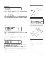
Install the winch on the desired side of the lift using:
2 – 3/8" x 4 hex bolts
4 – 3/8" flat washers
2 – 3/8" nylon lock nut
CAREFULLY thread the 25" red wheel onto the winch shaft. The wheel
should be able to thread on and off the shaft easily. This is the action that
activates the brake mechanism.
Turn the wheel clockwise and you should here a clicking sound, this
means the brake is working. This raises the lift and keeps it raised
wherever you stop.
Turn the wheel counter clockwise and the brake is released allowing the
lift to lower.
To keep the wheel from coming off the shaft fasten using:
1 – winch spring
1 – 1/2" jam lock nut
Tighten the nut just until 1 or 2 threads of the shaft are visible while prevent-
ing the winch shaft from turning.
winch 1500#
1
red wheel 25"
1
bolt package step 5
1
cradle 60.5"
2
cradle tie bar
2
pulley bar 63"
1
cradle spreader tube
2
cradle spreader end caps
4
bolt package step 4
1
NOTE
The wheel needs to thread on and off
the shaft to activate the brake. This
shaft should be greased yearly to
ensure proper operation.
Extreme care should be taken not to
cross thread and damage the threads
on the wheel hub. This will void your
warranty.


