


I456
GB
CS
01
18
7
G
B
PROTECTIONS
– The ADXL is equipped with a set of integrated protections to safeguard both the starter and the motor.
– Some of these are configurable. Their settings are to found in the P04 Protections menu.
– The following table summarises the available protections, and their parameters/alarms:
MOTOR THERMAL PROTECTION
– The ADXL is equipped with an electronic motor thermal protection, which can be configured in menu P04 Protections.
– The display shows the thermal status of the motor both numerically and graphically, and by convention displays 100% when the motor is running stably at nominal voltage and current (100%).
– When the current is >112%In (In = motor nominal current) the thermal status increases to its maximum value, which is 140%, and trips alarm A14 Motor thermal protection.
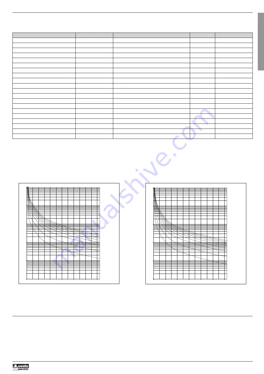
– The trip time is shown in the tables given below as a function of the overload current. The curves for the various graphs refer to the curve selected with parameters P04.02 and P04.03. The cold trip curves indicate
the trip time starting from thermal status 0%, while the hot trip curves start from thermal status 100%.
– With the motor stopped, the thermal status will tend to zero in a set time which depends on the configured class of thermal protection.
– The motor thermal protection alarm can be reset when the thermal status falls to or below the value of P04.04 Motor thermal protection reset, which has a default value of 120%. This value can be modified for
specific needs, without changing the trip time in any way.
– The motor's thermal status updates correctly even if there is no auxiliary supply to the control board.
MOTOR THERMAL PROTECTION VIA PTC
– The ADXL's IN3 input can be configured to connect to a PTC motor thermal protection sensor.
– The trip and reset values are conforming with DIN 44081.
– Tripping the sensor initiates the alarm A14 Motor thermal protection and stops the motor.
– The alarm can only be reset when the PTC sensor's resistance returns within the values defined by the standard.
STARTER THERMAL PROTECTION
– The display shows the numerical temperature of the heatsink/thyristors and graphically shows the thermal status of the starter.
– When the graphic bar reaches its maximum value, it trips the alarm A15 Starter thermal protection.
– The alarm resets automatically when the starter returns to an acceptable temperature.
PROTECTION MOTOR / STARTER PARAMETERS ALARMS COMMANDS
Three-phase line absent MOTOR - A01 -
No phase MOTOR - A02 -
Phase sequence MOTOR P04.11 A03 -
Frequency out of bounds MOTOR - A04 -
Auxiliary voltage fault MOTOR-STARTER - A05 -
Current asymmetry MOTOR P04.16 – P04.17 A06 -
Overcurrent MOTOR-STARTER - A07 -
Rotor jammed MOTOR-STARTER - A08 -
Load too low (dry running, minimum torque) MOTOR P04.08 – P04.09 A09 -
Starting time too long MOTOR P04.10 A10 -
Bypass relay fault STARTER - A11 -
Motor thermal protection pre-alarm MOTOR - A12 -
Starter thermal protection pre-alarm STARTER - A13 -
Motor thermal protection MOTOR P04.01-P04.02-P04.03- P04.04 – P04.05 A14 C02
Phases shorted STARTER - A16 – A17 -
Temperature sensor fault STARTER - A18 -
Line voltage too low MOTOR P04.12 – P04.13 A19 -
Line voltage too high MOTOR P04.14 – P04.15 A20 -
Maintenance interval MOTOR-STARTER P04.18 A22 C01
Fan fault / fans jammed STARTER - A23-A24 -
t
1000
100
10
1
Class 40
Class 35
Class 30
Class 25
1
Class 2
0.1
%
20
30
40
50
60
70
t
1000
100
10
1
Class 40
Class 35
Class 30
Class 25
1
Class
0.
%
10
20
30
40
50
60
70
Cold trip curves
Hot trip curves


