24
Assembling instrunctions and maintenance
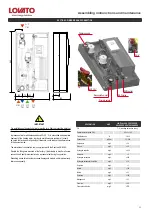
Attention
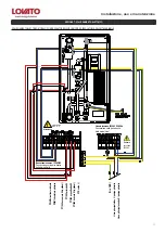
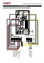
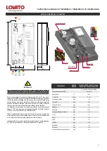
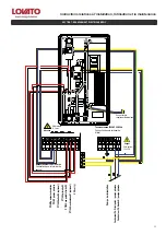
R1 relays: use only for standard pump control, 20 VA min. consumption
The polarity of the sensors is freely selectable.
The connection of the ground must be made to the lower
part of the terminal (-)
Protection line PE must be connected to the metal clamp PE!
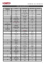
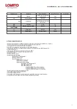
MFWC DIGITAL CONTROLLER CONNECTIONS
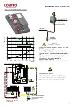
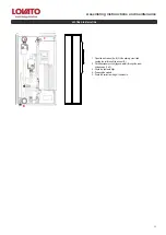
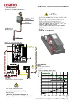
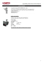
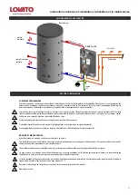
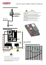
- Shut-off the flow closing the ball valves “DCW supply” ref. 1 and “DHW outlet”
ref.2
- Remove the cap (3/4”F ) to the T_Fast module as indicated in the pic.3.
- Install the recirculation kit (ref.4) screwing watertight the nut.
- Place the sensor into the pocket (see the image) and connect it to the
controller following the wiring diagram in the next section. In order to set the
parameters see the chapter “Electronic regulation”.
- Impostare i parametri di funzionamento del kit vedi capitolo “regolazione
elettronica”).
- Open the valves ref.1 and ref.2 and put the system under pressure.
- Input 230V.
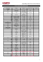
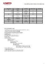
- Set parameters from the digital controller.
Ball valve
Pump type Wilo YONOS
PARA 15/7 PWM2
4
Sensor pocket for S2
recirculation sensor
Check valve
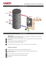
RECIRCULATION KIT CONNECTIONS AND START UP
DANGER!
POWERED DEVICE
1
2
3
Low voltage
max. 12VAC/DC
Connection on the left part of the terminal board!
Danger
Sensor side
max. 12 V
Attention
Main voltages 230VAC
50-60Hz
Connection on the right part of the
terminal board!
Main 230 V
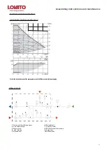
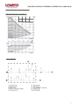
RECIRCULATION PUMP CHARACTERISTICS
For further informations about the pumps please read the Wilo manuals into the packaging
Q (
l/h
)
Δ
P (
m H
2
O)
!
!
Содержание 49060463
Страница 15: ...15 Installazione uso e manutenzione...
Страница 29: ...29 Assembling instrunctions and maintenance...
Страница 43: ...43 Instructions relatives l installation l utilisation et la maintenance...
Страница 57: ...57 Montage und Wartungsanleitung...

