


I456
GB
I
04
17
16
G
B
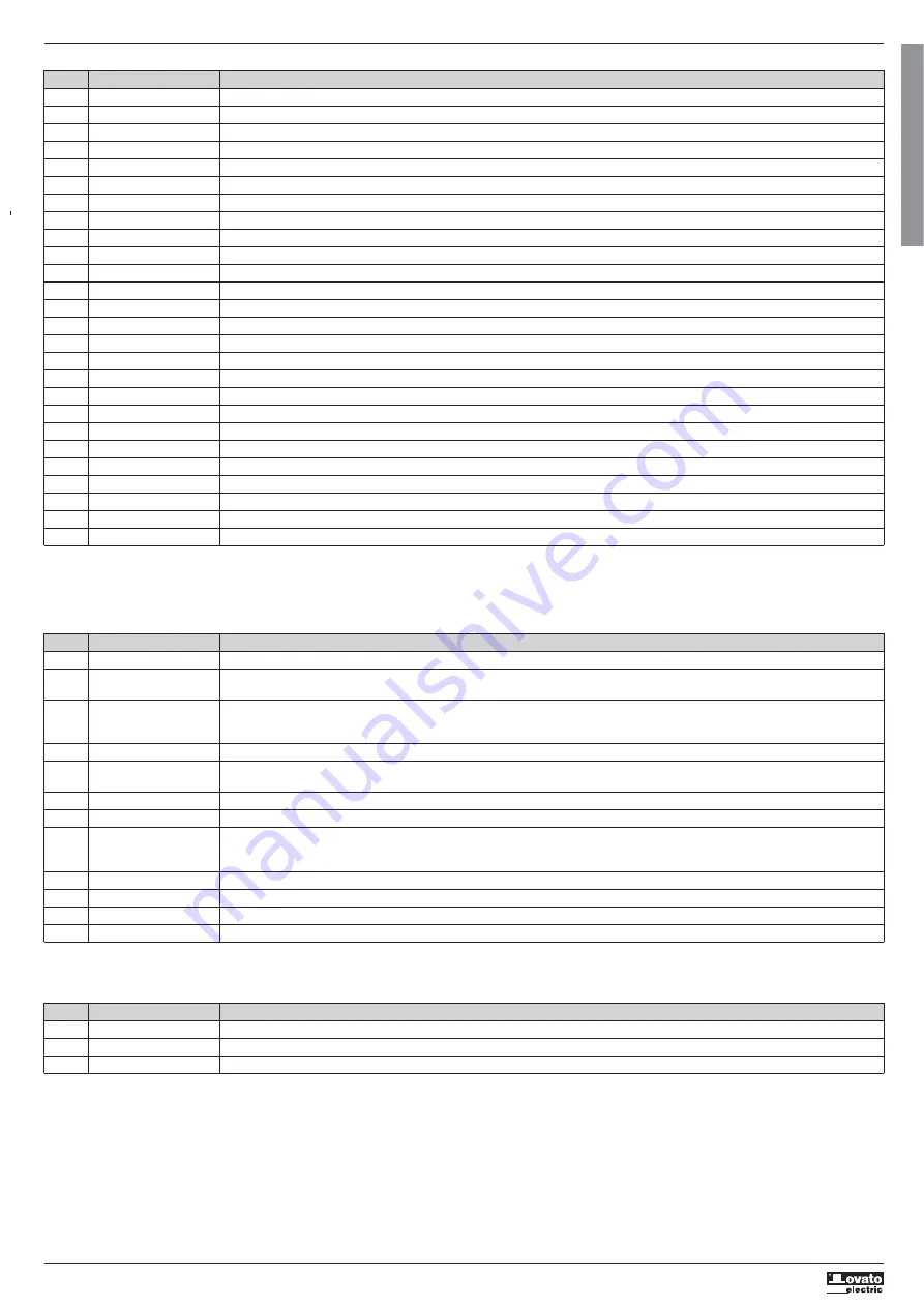
DESCRIPTION OF THE ALARMS
CODE DESCRIPTION REASON FOR THE ALARM
A01 NO POWER LINE All three phases are not present when start command given.
A02 PHASE LOSS One phase not present when start command given or when motor is running.
A03 WRONG PHASE SEQUENCE Phase sequence does not match the setting.
A04 FREQUENCY OUT LIMITS Frequency of line voltage outside of +-5% tolerance around 50 or 60Hz.
A05 AUX POWER FAILURE Voltage too low or micro interruption longer than the allowed one.
A06 CURRENT ASYMMETRY When the motor is running, current asymmetry greater than setting for time longer than setting.
A07 OVERCURRENT TRIP Current >750%Ie (soft starter current) for a time
200msec during starting.
A08 LOCKED ROTOR Current >500%In (nominal motor current) for a time
200msec during bypass.
A09 MOTOR LOAD TOO LOW Motor load torque lower than setting during bypass.
A10 STARTING TOO LONG Starting time (from start to bypass) longer than setting.
A11 BYPASS RELAY FAILURE Bypass relay contacts did not close or open.
A12 MOT. THERMAL WARNING Imminent motor protection trip with motor in bypass.
A13 STARTER TH. WARNING Imminent soft starter protection trip.
A14 MOTOR THERMAL TRIP Motor thermal protection tripped (inside soft starter or via PTC input).
A15 STARTER THERMAL TRIP Heatsink temperature greater than maximum allowed value.
A16 L1-T1 PHASE SHORTED SCR in short circuit or bypass contacts welded.
A17 L3-T3 PHASE SHORTED SCR in short circuit or bypass contacts welded.
A18 TEMP. SENSOR FAULT NTC internal temperature sensor for starter heatsink interrupted or broken.
A19 LINE VOLTAGE TOO LOW Line voltage L1-L3 lower than setting for set time.
A20 LINE VOLTAGE TOO HIGH Line voltage L1-L3 higher than setting for set time.
A21 MOTOR CURRENT TOO LOW Motor current <10%In (In = set nominal motor current) for all three phases.
A22 MAINTENANCE REQUEST Maintenance interval expired.
A23 COOLING FAN FAILURE No fans detected.
A24 COOLING FAN LOCKED Fan current too high, rotor probably jammed.
A25 SYSTEM ERROR Internal error. Please contact Lovato Electric customer service.
UA1..4 USER ALARM The user alarm was generated by the activation of the variable associated with menu P13.
NO. FUNCTION DESCRIPTION
0 OFF Disabled input.
1 START Motor start (mandatory: at least one programmable input must be configured with this function). When closed, it enables the starting.
It can be used both as a three-wire pulse command or two-wire continuous command (see connection diagrams).
2 STOP Motor stop. When opened, stops the motor either immediately or with a ramp. If a programmable input is configured with this function, it must remain closed to
provide the motor run enable signal, in combination with the above START input (see connection diagrams). If no input is configured with STOP function,
the START input provides both the run (closed) and stop (open) functions.
3 FREEWH. Freewheel: when active, no deceleration ramp is executed to stop the motor (even if programmed); the motor stops immediately.
4 PREHEAT. Preheating: enables the winding preheating function. A small current is injected into the motor to preheat the windings without making it rotate. It only works if the
thermal status is 0%.
5 COM. LOCK Commands lock: blocks input commands via the serial interface.
6 AL. INH. Alarms inhibition: Inhibits alarms with the Inhibit property active. It allows the user to disable some alarms selectively.
7 TS RESET Thermal Stauts reset: When the contact is closed, it forces the thermal status of the motor to 100%, if it is higher. In case of trip of the protection, it also provides
the reset, by allowing the reset of the alarm with the STOP command.
CAUTION: using this function affects the trip of the motor thermal protection and may cause the motor to overheat dangerously.
8 KBD LOCK Keyboard lock: blocks the functioning of the front keypad.
9 MOT. SEL. Motor Selection: for applications with multiple motors, selects which setting to use in menu P09 Multiple motors, using binary logic. See menu P09.
10 CONFIG. Configurable input. Used as a source for user alarms, for instance.
11 COMMAND It performs the command Cx of the commands menu. The number of the command to be executed is x, set in P06.n.02.
PROGRAMMABLE INPUT FUNCTIONS TABLE
– The following table shows all the functions which can be associated to the programmable digital inputs INPn.
– Each input may be set so as to have inverted function (NO - NC), with energising or de-energising delay with independent set times.
– Some functions require a further numeric parameter defined by index (x) specified by parameter P06.n.02.
– See menu P06 Programmable inputs for further details.
INPUT TERMINALS DEFAULT FUNCTION
INP1 IN1 START
INP2 IN2 STOP
INP3 IN3 OFF (disabled)
PROGRAMMABLE INPUTS DEFAULT SETTINGS
– The following table reports the factory default settings for the programmable inputs.
– If necessary, these settings can be modified with menu P06 Programmable inputs.


