Owners Manual
s
Rexnord
®
Planetgear™ 7000 Series Speed Reducers
(Page 22 of 32) Sizes Neptune, Neptune Plus, Orion Plus, Saturn Plus & Titan Plus
158-170
Rexnord
January 2015
3001 W. Canal St., Milwaukee, WI 53208-4200 USA
Supersedes 11-12
Telephone:414-342-3131 Fax: 414-937-4359 www.rexnord.com
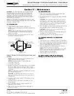
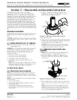
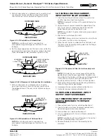
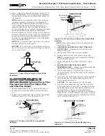
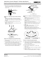
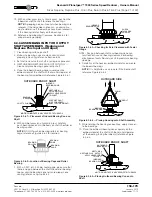
11. With an arbor press or a hydraulic press carefully push
bearing cone. When bearings begin to approach the
bearing cup, apply clean oil to outboard bearings.
NOTE
: DO NOT push on bearing rollers or bearing
cage; reference Figure 6.3.6.2.
12. Press outboard bearing until it touches the surface of
the bearing cup.
NOTE
: Do not over push bearings into cup. This might
cause the bearings to Brinell the cup.
NOTE
: An indication when the outboard bearing is
fully seated is when the hub will not rotate on the shaft
freely.
13. Clean and place the tongued washer onto the shaft.
14. Clean clampnut. Place it with the grooved side down
(or groove towards bearings) and thread on clampnut
until it is unable to rotate.
15. Mark the location of the clampnut.
16. Loosen clampnut approximately
¾
” (19 mm) from
original mark.
17. Tighten socket head cap screw on clampnut; reference
Table 14, Page 23.
18. Support hub and affix to work table with the shaft not
touching the table; reference Figure 6.4.1, next page.
19. With an arbor press or a hydraulic press, push on the
inboard end of the shaft to relieve the bearings.
NOTE
: A popping noise will sound when bearings are
relieved. If the noise does not occur , an alternative
way to determine if the bearings have been relieved is
if the housing rotates freely on the bearings.
20. Reference Axial Bearing Clearance, Section 6.4 for
proper bearing endplay.
21.
NEPTUNE AND NEPTUNE PLUS INPUT ONLY
—
After setting the axial bearing clearance, replace pipe
plug on housing near outboard end sealing it in the
process with thread sealant.
6.4 SETTING PROPER AXIAL BEARING
CLEARANCES ON INPUT OR OUTPUT
SHAFT ASSEMBLIES
6.4.1 MEASURING AXIAL CLEARANCE ON
INPUT AND OUTPUT ASSEMBLIES
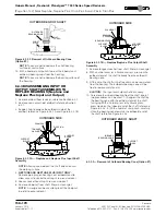
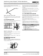
1. Support housing to allow the shaft to rotate freely;
reference Figure 6.4.1.
NOTE
: If necessary, the axial bearing clearance can be
measured by orientating the larger assemblies outboard
side down. The dial indicator should then be placed on
the inboard end of the shaft while prying upwards on
the outboard end of the shaft.
NOTE
: Axial clearance should be checked while seal
carrier is removed.
2. Affix the hub to the support table with C-Clamps or
bolting to table; reference Figure 6.4.1.
3. While exerting downward force by hand on the end of
the shaft, rotate shaft 6 to 10 times to align the bearing
rollers.
4. Use a dial indicator with a magnetic base to take
measurements.
NOTE
: Use a dial indicator that has a balanced dial with
0.0001” or 0.010 mm graduations.
5. Affix the magnetic base of the dial indicator to a flat
area of the housing; reference Figure 6.4.1.
6. Place the stem of the dial indicator perpendicular to the
end of the shaft.
NOTE
: Place stem of dial indicator as close to the
center of the shaft as possible.
7. Record the reading of the dial indicator when the
indicator has engaged the shaft.
8. With a pry bar, push the inboard end of the shaft up;
reference Figure 6.4.1.
NOTE
: Use a constant swift force when pushing on the
pry bar. Excessive force not required. DO NOT rotate
shaft while pushing on shaft. The object is to lift the
shaft only.
9. Record reading of the dial indicator. Take the difference
between the two readings. The difference is the axial
bearing clearance.
NOTE
: 0.001” to 0.004” ( 0.025 to 0.102 mm) axial
bearing clearance is recommended. Do steps 3 thru 9
several times to insure an accurate measurement has
been made.
10. See Sections 6.4.2 and 6.4.3 for adjusting for too much
or too little axial bearing clearance.
6.4.2 ADJUSTING FOR TOO MUCH AXIAL
BEARING CLEARANCE
NOTE
: If axial bearing clearance is too excessive, it might
be necessary to remove the clampnut and other hardware,
and press the bearing again. Reference Section 6.3.5 -
steps 11 to 20, or Section 6.3.6 - steps 12 to 21.
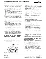
1. Loosen socket head cap screw on clampnut.
2. Mark the position of the clampnut.
3. Rotate clampnut 1/16” to 1/8” (1.5 to 3.1 mm) in the
clockwise direction from mark to tighten clampnut.
NOTE
: The measurement given is an estimate.
4. Follow procedures in Section 6.4.1 to determine new
axial bearing clearance.
5. Repeat first 5 steps if axial bearing clearance is found
to be still too much.
OUTBOARD END OF SHAFT
DIAL INDICATOR
HUB
C-CLAMP
SUPPORT
BLOCK
PRY BAR
SUPPORT
BLOCK
C-CLAMP
MAGNETIC
BASE
Figure 6.4.1 Setting Axial Bearing Clearance
Содержание CD-1261
Страница 1: ... 0 1 2121 3 4 1 5 6 ...
Страница 2: ... ...
Страница 3: ... ...
Страница 4: ... ...
Страница 5: ... ...
Страница 6: ... 0 1 2 3 4 5 6 5 6 7 1 1 5 6 5 6 5 6 1 0 0 ...
Страница 7: ... ...
Страница 8: ... 0 1 2 0 3 0 ...
Страница 9: ... ...
Страница 10: ... 0 12 2 0 3 4 5 5 5 0 0 ...
Страница 11: ... 6 12 0 0 7 5 5 0 8 0 8 5 0 50 9 4 12 0 0 9 4 0 9 64 0 5 0 0 1 0 0 ...
Страница 12: ... 0 2 0 0 3 0 6 6 6 6 6 0 0 0 5 5 0 6 0 ...
Страница 14: ... ...
Страница 15: ... 0 0 1 1 2 1 1 3 0 4 5 1 0 1 0 0 2 1 2 1 0 0 0 2 1 1 1 1 1 0 0 0 1 0 0 0 1 0 1 6 1 1 ...
Страница 17: ... 1 0 3 0 0 1 1 1 71 0 0 1 1 1 0 1 1 ...
Страница 18: ... ...
Страница 21: ... 1 A 0 0 1 7 0 0 1 1 7 2 1 2 1 B1 7 0 1 7 1 1 C 1 A 1 4 1 0 D199 5 6 1 4 1 A 1 81 0 0 0 0 1 7 1 1 1 ...
Страница 25: ... 8 ...
Страница 26: ... E 4 0 1 A 4 1 1 A 0 1 0 4 1 0 0 1 7 0 1 0 0 0 1 0 0 1 0 1 01 1 0 4 0 0 0 1 0 0 1 G 7 1 4 0 1 1 ...
Страница 28: ... 1 7 4 0 4 1 4 1 1 4 1 1 1 4 85 4 4 1 4 1 4 0 6 4 1 1 1 01 0 1 4 6 4 1 1 4 L 1 ...
Страница 29: ... 4 ...
Страница 30: ... 0 1 2 3 24 3 5 6 4 5 6 4 5 5 1 5 4 74 8 5 9 1 4 27 3 5 4 74 8 5 5 29 13 27 3 1 29 13 5 1 ...
Страница 31: ... 8 8 80 1 2 3 5 6 4 5 6 4 5 5 1 5 A 9 1 B 4 27 3 888 7 8 0 B 4 C D 5 29 13 B 27 3 888 7 29 13 ...
Страница 32: ... 4 24 3 5 6 4 5 6 4 5 5 4 7 M 7 4 7 N 2 0 7 2 M 0 N M ...
Страница 35: ... 8 G 8 0 G 4 88 8E 1 2 3 5 6 4 5 6 4 5 5 1 4 1 4 27 3 1 088 7 5 4 1 5 29 13 H 27 3 088 7 ...
Страница 36: ... E 5 ...
Страница 37: ... 9 4 5 H 0 1 2034 2034 2034 2034 0 5 1 6 71 6 1 2 1 1 1 0 1 81 1 9 9 ...
Страница 38: ... 1 5 1 5 1 3 05 3 1 0 1 1 6 A 6 1 A 6 B 1 6 B 6 1 1 1 6 6 6 2 9 0 6 ...
Страница 39: ... 0 ...
Страница 40: ... 0 0 ...
Страница 42: ......
Страница 43: ... 0122 3 4 5 6 4 4 4 4 5 4 4 4 4 4 7 7 4 4 6 4 4 5 5 4 5 8 8 3 5 3 5 3 5 3 5 5 ...
Страница 44: ... 0 0 0 0 0 0 0 0 0 0 1 1 2 3 0 3 3 0 0 33 0 3 0 3 3 0 ...
Страница 45: ... 011 2 3 4 5 5 3 2 3 2 3 5 5 5 5 5 55 2 3 5 2 6 2 6 6 5 6 6 5 6 5 2 6 5 6 2 2 2 2 2 5 5 2 2 2 2 7 5 ...
Страница 46: ... 011 2 3 3 4 3 2 5 5 6 ...
Страница 47: ... 011 2 3 4 5 3 6 3 7 7 2 4 ...
Страница 48: ... 00 1 2 3 4 3 5 5 5 5 5 3 1 1 2 2 6 1 1 1 5 5 7 5 5 5 5 ...
Страница 49: ... 0122 3 4 5 6 7 4 8 4 4 8 4 4 8 5 5 5 5 5 5 5 5 5 5 5 5 ...
Страница 50: ... 0 11 2 2 2 2 2 3 4 5 0 5 3 6 7 6 6 8 9 8 9 6 6 8 9 0 1 1 1 1 1 8 9 1 1 1 5 ...
Страница 51: ... 011 2 3 4 5 4 2 2 2 6 2 6 6 3 3 3 3 3 3 3 ...
Страница 52: ... 011 2 3 2 4 5 3 5 5 5 5 6 5 3 22 7 22 3 22 7 22 7 5 22 7 7 7 5 5 5 5 2 5 5 52 5 2 2 5 2 5 2 5 2 ...
Страница 53: ... 011 2 3 4 5 4 2 6 33 2 33 6 6 6 ...
Страница 54: ... 011 2 3 3 3 3 4 5 4 33 2 33 6 3 3 3 ...
Страница 55: ... 0122 3 4 5 6 7 4 4 5 7 7 7 7 55 55 55 4 4 7 4 7 4 7 7 4 4 8 4 55 8 4 8 7 4 8 8 8 7 7 7 5 7 7 6 ...
Страница 56: ... 0122 3 4 5 6 7 8 4 4 5 8 4 4 8 9 9 9 8 4 4 4 88 8 8 8 ...
Страница 57: ... 0 1 1 1 2 1 3 1 1 1 0 1 1 1 4 1 1 ...
Страница 58: ... ...
Страница 59: ... ...
Страница 96: ...Bearing Maintenance Guide x Lubrication x Troubleshooting ...
Страница 97: ......
Страница 98: ......
Страница 99: ......
Страница 100: ......
Страница 101: ......
Страница 102: ......
Страница 103: ......
Страница 104: ......
Страница 105: ......
Страница 106: ......
Страница 107: ......
Страница 108: ......
Страница 109: ......
Страница 110: ......
Страница 111: ......
Страница 112: ......
Страница 113: ......
Страница 114: ......
Страница 115: ......
Страница 116: ......
Страница 117: ......
Страница 118: ......
Страница 119: ......
Страница 120: ......
Страница 121: ......
Страница 122: ......
Страница 123: ......
Страница 124: ......
Страница 125: ......
Страница 126: ......
Страница 165: ... 0 0 1 2 3 4 5 6 52 3 52 3 7 8 4 6 52 4 6 1 9 9 9 9 9 ...
Страница 166: ... 0 5 9 9 2 2 4 6 4 6 4 6 7 8 7 8 2 4 6 4 7 8 7 8 2 4 6 4 6 52 A ...
Страница 167: ... 0 0 1 2 1 2 3 4 2 1 2 3 4 ...
Страница 168: ... 0 2 1 2 3 3 4 2 1 2 3 4 2 ...
Страница 169: ... 0 255 02 9 B 29 529C C 2 9 3D 29 E 25 9 F 9B C D 33 A 9 3 2 D D D B G D 0 3 5 0 23B 9 3 3 2 D 90 5 9 3 3 3 D A2 2 D ...
Страница 194: ......
Страница 195: ......
Страница 196: ......
Страница 218: ......
Страница 219: ......
Страница 234: ...15 Notes Model 121 Regulators Brochure ...
Страница 236: ......
Страница 324: ... 6PDUW QIUDVWUXFWXUH 1 HQ LPHQVLRQV FRQW G 1RW WR VFDOH 9 9 6 9 0 5 3 7 8 1 2 4 9 4 9 4 4 SOXJ P HQ 9 LPHQVLRQV ...

