16
3DM
®
-CX5-10
USER MANUAL
4.1 Direct Sensor Measurements (IMU Outputs)
The sensors in an Inertial Navigation System (INS), from which measurements for navigation
and orientation are obtained, are collectively known as the Inertial Measurement Unit (IMU).
These sensors are arranged on the three primary axes (x, y, and z) to sense angular rate
acceleration. The gyroscopes are used to adjust the current attitude estimate when an
angular rate is sensed. The accelerometers sense gravity as well as linear acceleration.
All measurements are temperature- compensated and are mathematically aligned to an
orthogonal coordinate system.
The IMU sensors can be read directly to report standalone inertial measurements or computed
measurements. Because the sensor system is digital, the analog voltage readings from the
sensors are converted into a digital equivalent value based on the volt-to-bit scale of the
internal analog-to-digital voltage converter. In the MIP Monitor software the conversion values
are not configurable, but there are user-settable options for how the measurement is made.
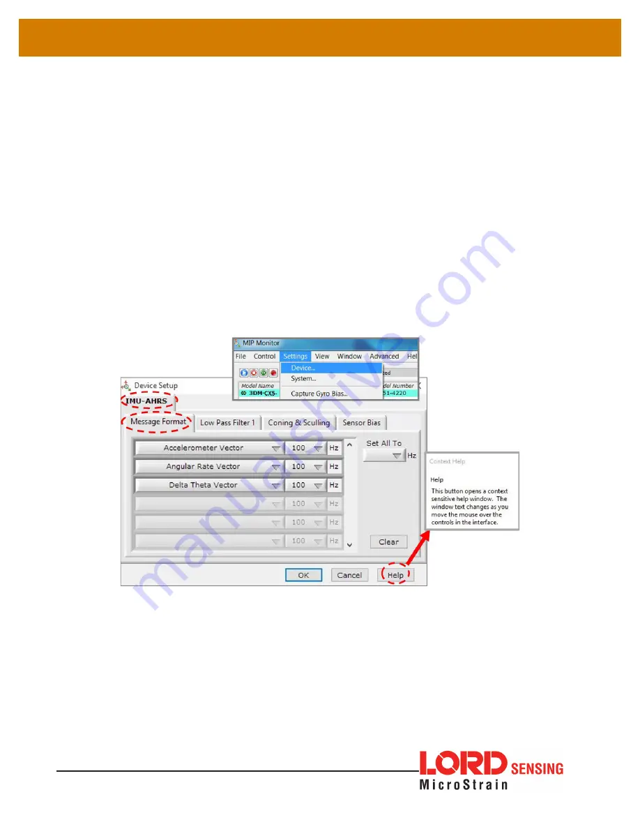
These settings are available at: Settings > Device > IMU (tab). With the Help window open
(accessed with the Help button), mousing over context-sensitive settings provides a detailed
explanation of the setting.
Figure 15 - IMU Settings
Table 2 - IMU Measurements
lists the IMU measurements available for the 3DM-CX5-10.
Additional measurement units may be available in MIP Monitor for some outputs, however
they are converted values and do not represent the actual sensor outputs. Only actual output
units are listed.


