background image

47

B1001

WORKING INSTRUCTIONS

LOG STACK

Do not stack the logs higher than 1 m.

Logs that are soiled, sandy, muddy or dirty 
considerably shorten the life of the band blade and 
increase the risk of blade breakage. Avoid dragging 
the logs over the ground and try to keep the logs as 
clean as possible.

It can also be a good idea to separate different sorts 
of wood into different log stacks.

LOG TABLE

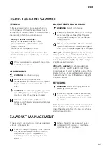
It is possible to load logs from both sides of the 
band sawmill. If the log stack is placed on the same 
side as the operator’s side, the log stack must be 
secured before every occasion of sawing.

Build the log table so it is the same height as the 
cross bunks on the band sawmill. If the log table 
is placed on the left side of the band sawmill, it 
should end 10 cm from the band sawmill. If the log 
table is placed on the operator’s side, it should end 
approx. 1 m from the band sawmill and you should 
use a removable ramp between the log table and 
the sawmill. Ensure that the rear of the log table has 
large wedges to prevent the logs from rolling off 
from it.

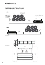
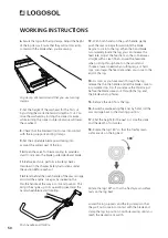
Ensure that the logs closest to the band 
sawmill are secured with heavy-duty straps 
so that they can not roll towards the sawmill 
while the sawmill is running. [

See illustration 2

]

LOADING LOGS

WARNING! 

Risk of crush injuries between log 

and band sawmill.

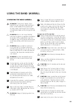
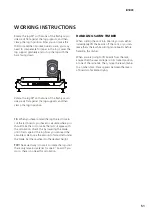
Always stand at the side of the log table when 
handling logs [

see illustration 3, area A

]

Avoid standing between the log table/log stack 
and the band sawmill. The log stack must 
always be secured with reliable straps when 
you are within area B [

see illustration 3

].

The logs should be rolled from the log table. 
Do not drop them onto the band sawmill.

When loading a log:

1. Position the saw carriage at its rearmost position 
on the rails (the ’home’ position).

2. When loading the log from the operator’s side, 
raise the log supports to their highest position. 
When loading the log from the left side of the band 
sawmill, the log supports have to be moved to the 
opposite side of the bed (the operator’s side). Then, 
fit them in their highest position. When the log lies 
stably on the bed, refit the log supports to the left 
side of the band sawmill.

3. If you use a removable ramp, it should be built 
and positioned so that there is no gap between the 
log table and the band sawmill.

4. Untie the straps that secure the front of the log 
pile.

5. Roll out a log.

6. Retie the front logs with the straps.

7. Carefully roll the log up against the log supports. 
Use a log turner/rotator. Centre the log laterally over 
the log bed cross bunks.

8. Adjust the log supports so that they support the 
log, but will not come into contact with the band 
blade when you are sawing. Lock the log supports in 
position.

9. Adjust the log clamps so that they come in the 
same position as the log supports, but on the 
opposite side of the log. Adjust the height of the log 
clamps to secure the log. Ensure that the log clamps 
will not come into contact with the band blade 
when you are sawing.

Содержание B1001 G2

Страница 1: ...contents before you use the machine This user manual contains important safety instructions WARNING Incorrect use can result in serious or fatal injuries to the operator or others TRANSLATION OF ORIGINAL USER MANUAL USER MANUAL LOGOSOL B1001 G2 EN Ref no 0458 395 5301 REV 9 ...

Страница 2: ...most to meet your expectations Logosol has been manufacturing sawmills since 1989 In that time we have supplied approximately 50 000 machines to satisfied customers the world over We care about your safety as well as we want you to achieve the best possible results with your sawmill We therefore recommend that you take the time to carefully read this user manual from cover to cover in peace and qu...

Страница 3: ...d on the rail frame 19 Final assembly of sawhead Briggs 23 hp 22 Final assembly of sawhead electric motor 12 kW 28 Order of adjustments 31 Other adjustments 37 The functions of the sawmill 40 Wiring diagram 42 Using the band sawmill 43 Sawdust management 45 Start stop instructions 46 Operation instructions 47 Maintenance 52 Troubleshooting 55 CE Declaration of conformity 56 TABLE OF CONTENTS ...

Страница 4: ... integral parts of the band sawmill and should always be kept together with it They should also follow the band sawmill if it is sold Responsibility for the band sawmill being correctly assembled and put into operation and being used in a safe way lies solely with the person s who assembles and uses the band sawmill GENERAL INFORMATION DESCRIPTION OF THE BAND SAWMILL ...

Страница 5: ...LL Saw carriage Sawhead height crank Adjustable blade guard Push handle Throttle Log support Log clamp Cross bunk Band wheel guard Blade tension handle Blade cooling tank Fuel tank Depth of cut scales Lift rings Machine label Rail end stop Leveling foot ...

Страница 6: ...ndling band blades and some of the plates Band blades and motor parts may be hot after sawing Always use approved hearing protection when working with the machine Even short exposure to high frequency noise can damage your hearing Always use closefitting safety goggles when working with the machine or handling band blades Under certain circumstances the use of respiration protection may be necessa...

Страница 7: ...lity alertness or otherwise cause negative side effects THE WORKSITE WARNING Never operate a band sawmill with a petrol powered engine in enclosed or poorly ventilated areas This can result in death due to suffocation or carbon monoxide poisoning Only operate the band sawmill and handle band blades in full daylight or under adequate lighting Keep the work area free from clutter pets children obsta...

Страница 8: ... SAW CARRIAGE Length 1100 mm Width 2250 mm Height 1980 mm Weight 210 kg Volume of water tank 17 75 litres Feed rate Manual CAPACITY Max log diameter 1001 mm Max sawing width 850 mm Effective sawing length standard 4 85 m BAND BLADE TYPE AND SIZE 4310x33 pitch 22 mm Band wheel diameter 500 mm Band wheel rotation speed 1000 rpm Blade speed 30 m s SAWMILL MOTORS Electric motor 12 kW 400 V weight 65 k...

Страница 9: ... Lock Countersunk Dome ADDITIONAL SYMBOLS Allen bolt Partial thread Allen bolt Partial thread hex bolt Hex bolt Partial thread flange bolt Flange bolt Carriage bolt Shoulder bolt Phillips bolt Slotted bolt Set screw Hex nut Flat washer Flange nut BOLTS NUTS Diameter DIAMETER LENGTH Length This symbol describes the sawing direction and reappears during assembly This symbol describes the recommended...

Страница 10: ...3 02008 2x 03 01972 4x 01 00232 1x 03 01973 14x 03 01977 2x 02 00247 1x 03 02180 4x 03 01857 2x 8300 005 0005 1x 8300 005 0150 1x 8300 005 0100 1x 8300 005 0010 8300 005 0030 8300 005 0040 8300 005 0020 58 x M8x16 58 x M8 4 x M8x25 4 x M8x12 10 x M8x20 10 x M8 2 x M8 20 x M16 16 x M12x90 16 x M12 16 x M12 COMPONENTS ...

Страница 11: ...200 9291 020 0005 03 02181 03 02007 03 01905 03 01982 9034 011 0002 03 01465 9029 011 0001 03 01464 9026 015 0002 6x 2x 4x 2x 4x 32 x M12x140 32 x M12 4 x M6x65 6 x M8x95 4 x M6 4 x M6 8300 005 0050 8300 005 0060 8300 005 0300 COMPONENTS ...

Страница 12: ...wmill by mounting the rails The sections of rail are place under the saw head in the pallet Assembly involves heavy lifting and it requires two people to help with the work There are accessories for this machine that may affect the sequence of assembly in this manual Read through the assembly instructions in the various manuals before starting work to get an overview of the different procedures EX...

Страница 13: ...eginning the assembly and then follow the step by step instructions during the assembly Follow the steps of assembly carefully and use an ergonomically correct work position while working Work on level ground as this will facilitate when adjusting the rails When installing trailer kits and accessories that require fixed support legs skip step 1 see manual for current product ...

Страница 14: ... 5 6 16 x M12 16 x M12x90 16 x M12 3 2 1 4 8300 005 0040 78 5mm 8300 005 0050 If the machine is to be equipped with hydraulics these two cross bunks should not be installed at this point of assembly Now repeat steps 2 5 for the other rail ...

Страница 15: ...15 B1001 8 10mm 8 10mm 4 x M8x16 4 x M8x16 38 x M8x16 4 x M8 4 x M8 38 x M8 7 8 9 8300 005 0010 8300 005 0010 8300 005 0010 ...

Страница 16: ...tions should overlap each other Tighten the bolt joints fingertight before the final adjustmen of the rails Repeat this process on each corner The rail sections should be fitted so that they overlap each other They are then secured with the bolt joints in every rail attachment hole in the rail frame as shown in the illustration Then repeat the installation on the other side of the rail frame The l...

Страница 17: ...x12 4 x 12 x M8x16 12 x M8 6 x M8x20 6 x M8 4 x M8x25 4 x M8x20 M8x20 4 x M8 6 x 2 x 2 x 2 x BRB M8 12 13 14 15 8300 005 0020 8200 005 0200 8300 005 0010 8300 005 0020 8300 005 0020 8200 005 0200 2 x 2 x 2 x 1 3 M8x25 ...

Страница 18: ...d put some extra time into this step When the rail is adjusted level check that all the rail sections are level at the joints and that the inner and outer rail sections are at the same height All joints should be as level as possible Adjust and tighten the bolting step by step When one side of the rail frame is adjusted along its whole length and the joints are level tighten all boltings on this s...

Страница 19: ...ith the help of a for this situation appropriate lifting device When the sawhead is installed onto the rails the anti tip wheels must be fitted to the sawhead frame Make sure that the sawhead frame clasp the rails INSTALLING THE SAWHEAD ON THE RAIL FRAME Important Start by removing the flange nuts outside the bogie tube they will be needed in step 3 Leave the screw in place it will be needed later...

Страница 20: ...20 2 x M6x65 3 x M8x95 2 x M6 2 x M10 2 x M6 2 x 2 x 0 2 3 4 5 8300 005 0300 8300 005 0060 Use existing nuts from step 1 Repeat steps 1 4 on the other side ...

Страница 21: ...21 B1001 6 7 12kw This step 6 is not to be performed if the machine is to be equipped with Smart Set see Smart Set manual Use the pre fitted screws for this assembly Smart Set MOUNTING THE HANDLE ...

Страница 22: ...ad before the sawhead is placed on the rails Be two people when the engine is lifted in place Mount the engine on the motor bracket and slide in the centrifugal clutch through the hole in the back of the band wheel guard The illustration below shows the hole pattern used for the Briggs 23 hp engine Install the manifold and muffler on the engine FINAL ASSEMBLY OF SAWHEAD BRIGGS 23 HP ASSEMBLY ENGIN...

Страница 23: ...3 1 x 9020 011 0091 1 x 8000 001 6054 1 x 8000 001 6057 1 x 8000 001 6060 4 1 x M6x50 1 x M5x50 1 x M6 1 x M5 BRIGGS 23 HP Fit the the throttle handle to the tube handle This assembly 3 4 is not to be performed if the machine is to be equipped with Smart Set see Smart Set manual Smart set ...

Страница 24: ...f the throttle attachment points and remove the throttle from the engine Then remount the valve cover Loosen the throttle wire bolt on the front of the engine and remove the wire end from the wire holder Facilitate this step by using a pair of pliers to remove the wire end BRIGGS 23 HP This assembly 6 7 is not to be performed if the machine is to be equipped with Smart Set see Smart Set manual Con...

Страница 25: ...ce on the machine Start by setting the throttle cable adjustment at the throttle handle so that you have equal adjustment allowance in both directions 1 Attach the other end of the cable sheath to the engine clamp 2 Screw the cable to the nipple 3 Make sure that the throttle is in the neutral unaffected position when doing this Make sure that you have 1 3 mm of play in the throttle handle and that...

Страница 26: ... machine Fit the interlock safety switch hinge on the side of the cover where no hinge is yet fitted Note that the power cord should point towards the centre of the engine shelf Connect the safety switch to the engine as in the illustration Connect point to the lower connector on the engine Then secure point with the upper bolt This is how you check the safety function Start by opening the wheel g...

Страница 27: ...e user manual Then connect it to the male connector the positive wire Connect the positive wire to the output of the generator Connect the other end to the battery plus pole INSTALLATION ELECTRIC START Connect the ground wire to the engine ground point Connect the other end to the negative pole of the battery Place the battery in the protective box and fasten it with a strap as shown below BRIGGS ...

Страница 28: ...afety switch installed Now the electric motor has to be mounted on the motor bracket and the belt pulley and the drive belt have to be installed Follow the assembly instructions and then the instructions under the section Order of adjustments in the sawmill user manual when the assembly is finished ASSEMBLY ELECTRIC MOTOR FINAL ASSEMBLY OF SAWHEAD ELECTRIC MOTOR 12 KW ...

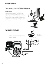
Страница 29: ...x16 1 2 3 1 x M5x50 2 x M5x16 6 x 6x16x1 3 x M5 1 x 9038 013 0003 1 x 9038 013 0004 1 x 1 x 03 01988 4 035 035 040 040 Possibility of phase change to change the direction of rotation of the motor ELECTRIC MOTOR 12 KW ...

Страница 30: ...o the machine To start the motor press and hold the enabling switch right button Then press the start button left button When the motor has started you can release the start button The motor will run until you release the enabling switch STARTING THE MOTOR CONTROL PANEL SWITCH ON OFF ELECTRIC MOTOR 12 KW ...

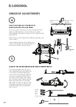
Страница 31: ...her machine settings Due to this it is crucial that you follow the order outlined below Adjust the levelness of the rail frame Adjust the parallelity between the band blade and the cross bunks Adjust the adjustable blade guide horizontally Adjust the band wheels Adjust the parallelity between the band blade and the rails Tensioning the throttle wire The lengthwise position of the blade Adjust the ...

Страница 32: ...n of the feet by tightening the counter nut inside the rail frame ADJUST THE LEVELNESS OF THE RAIL FRAME ADJUSTMENT OF THE LEVELLING FEET ORDER OF ADJUSTMENTS The angle of the band wheels has to be adjusted so that they are at right angles to the cross bunks With the sawhead in its lowest position check the perpendicularity between the band wheels and the cross bunks A good method is to place a se...

Страница 33: ...rs to the part of the blade that is between the gullet and and the back of the blade If the blade bends in the direction of the saw teeth the blade is positioned too far forward on the wheels If it bends in the other direction the blade is positioned too far back First install the blade centred over the drive belt so that blade body protrudes equally on both sides of the drvie belt Then tighten th...

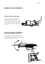
Страница 34: ...Y BETWEEN THE BAND BLADE AND THE CROSS BUNKS ORDER OF ADJUSTMENTS The adjustable blade guide with guard has to be adjusted to ensure straight cuts in all positions Install the blade guide rollers Then bring the blade guide with guard to its innermost position Place a spirit level on the blade guide and adjust by turning the eccentric handle until the blade guide with guard is horizontally level Wh...

Страница 35: ...ration Ensure that the blade guide arm is aligned between the wheels and runs without play To adjust the parallelity between the blade guide arm and the band blade you loosen the three fixing bolts on the outside of the blade guard holder Then adjust the parallelity using the adjusting bolt on the rear plate TIGHTEN THE BLADE GUIDE ARM ADJUST THE PARALLELITY BETWEEN THE BLADE GUIDE ARM AND THE BLA...

Страница 36: ...il the measurements are the same at both measurment points One method to facilitate adjusting is to use the value from meas urement point 1 compare it with the value from measurement 2 and then by raising or lowering the blade guide adjust half the difference at measure ment point 2 When the blade is parallel to the rails repeat the adjustment steps on the other blade guide roller ADJUST THE PARAL...

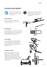
Страница 37: ...e carried out in a particular order Read all the adjustment instructions before beginning adjusting and then follow the step by step instructions while adjusting Tension the blade by turning the T handle clockwise Read the blade tension scale which is located inside the band wheel guards Tension the blade until the red line is aligned with the two arrows in the opening for the blade tension spring...

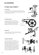
Страница 38: ...checking point OTHER ADJUSTMENTS The sawmill water tank has to be refilled before operation Refill through the opening in the back of the saw carriage The volume of the tank is 17 litres WATER TANK To ensure that the scale on the sawhead crank works correctly it has to be calibrated This is done by lowering the sawhead to its lowest position and then loosening the adjusting plate of the crank Now ...

Страница 39: ...gine OTHER ADJUSTMENTS ADJUSTING THE CRANK SPRING PREPARING THE ENGINE BEFORE STARTING UP BLADE GUIDES The blade guides tension the blade so that it comes 3 mm below the band wheels The blade guides can adjust the angle of the blade measured in the direction of the cut by adjusting the top and bottom adjusting bolts The blade guides must be adjusted so that they are parallel to the back of the bla...

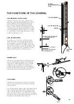
Страница 40: ...en a board is cut above the blade you have to compensate for the kerf i e 1 8 The wood piece below the blade never needs to be kerf compensated It has the same measurement as the one shown on the absolute scale on the front leg of the carraige This is how you use the crank scale when adjusting depth of cut Example 1 If you are going to cut a 1 board and the crank scale shows the number 3 you first...

Страница 41: ... against the log This is done by turning the eccentric plate clockwise Then to secure the log you turn the handle on the clamp clockwise as shown in the illustration To release the tension carry out the steps in reverse order and turn the plate and the handle counter clockwise LOG CLAMPS THE FUNCTIONS OF THE SAWMILL THE FUNCTIONS OF THE SCALES LAST CUT INDICATOR The sawmill has two scales one mill...

Страница 42: ...d by a lever located on the side plate at the operator side In its start ing position the lever points at a right angle from the side plate To release the water flow the lever is pulled back The flow of the water cooling is controlled by moving the cool ing tube in the narrowing slot in the motor bracket Move the tube inwards or outwards in the slot until you reach the desired cooling level THE FU...

Страница 43: ... to call for help WARNING Danger of flying fragments from dirty logs Always inspect the logs so that there are no objects wedged in the bark before sawing Never stand between the pile of logs and the band sawmill Always stand at the side of the pile of logs when handling the logs Never stand where you are at risk of being hit by a rolling log Danger area of the machine Minimum safety distance arou...

Страница 44: ...nd in the right direction Before each cut Ensure that no other persons than the operator and no pets are within the danger area of the machine the worksite is free of objects that can pose a tripping hazard or distract the operator the band blade runs clear of the log supports and log clamps the rails are free of debris dirt etc the log is firmly secured the adjustable blade guard has been correct...

Страница 45: ...be lifted or transported when assembled together but must be transported separately as two parts Lifting the saw carriage Disconnect the carriage s anti tip wheels one on each side and lift the carriage with the help of reliable lifting gear affixed to the lift rings located at the top of the carriage Weight see Technical data Lifting the rails bed Use a hand pallet truck or a forklift truck and l...

Страница 46: ... by squeezing the throttle handle all the way in to its end position This brings the engine up to its operating speed and the band blade starts rotating 6 If the choke is in its closed position gradually move the control lever towards its open position as the enging gets hotter STOP You stop the band blade by releasing the throttle on the push handle The band blade will then slow down and stop and...

Страница 47: ... illustration 3 area A Avoid standing between the log table log stack and the band sawmill The log stack must always be secured with reliable straps when you are within area B see illustration 3 The logs should be rolled from the log table Do not drop them onto the band sawmill When loading a log 1 Position the saw carriage at its rearmost position on the rails the home position 2 When loading the...

Страница 48: ...ecuring the logs at the rear edge of the log table Secured logs at the front of the log pile Logs Log table The right side operator s side of the rails must be kept clear ALT 1 ALT 2 Illustration 2 WORKING INSTRUCTIONS Illustration 3 ...

Страница 49: ... the saw carriage back through the cut WARNING Read and follow all the safety instructions described in the chapter Safety Instructions under the section Before each cut 1 Before operating the sawmill perform all safety checks described in the chapter Safety Instructions under the section Every time before operating the band sawmill 2 Raise the log supports by unhitching them then lifting them to ...

Страница 50: ...ush the saw carriage forward until the blade begins to cut into the log When the band blade is completely inside the log you can increase the feed rate Adjust the feed rate so the cut becomes straight with a clean finish Lower the feed rate when cutting through knots in the wood and choose a lower speed when cutting large or hard logs Also lower the feed rate when you come to the end of the log 14...

Страница 51: ... the amount of wood left under the blade Set the sawhead to the desired height TIP The easiest way is to wait to rotate the log until there only remains material for one 2 board If you do so there is no need for calculation HANDLING SAWN TIMBER When cutting the cant into boards you can either immediately lift the boards off the cant or you can leave them there while cutting more boards before hand...

Страница 52: ...lades etc on the band sawmill that can produce sparks or flames near the engine fuel tanks fuel or other flammable material If you spill fuel on the machine when refueling wipe this up immediately If you get any fuel on your clothes change clothes immediately Never operate the engine if there is a fuel or oil leak Always turn the engine off before refuelling MAINTENANCE The regular maintenance tha...

Страница 53: ...and Adjusting the position of the blade on page 33 3 Close the guards over the band wheels 4 Lock the guards LUBRICATION POINTS In order to keep the sawmill in good condition for many years and to have a problem free ownership it is important to lubricate the sawmill components as describred below Lubricate immediately after assembly before starting to use the sawmill Lubricate every 50 hours of o...

Страница 54: ...s neutral position when released so that the engine goes down to idle If not lubricate the throttle wire with Super Flo SKU 9999 000 5115 Check that the interlock safety switch in the hinge of the band wheel guards works Check by opening the band wheel guards while the engine is turned off and listen for the safety switch disconnecting Check that the emergency stop shuts down the engine ignition l...

Страница 55: ... new ones Uneven board thickness The log bed flexes due to insufficient support Support the rails log bed as outlined in the instructions in this manual The blade does not track correctly and slips off the band wheels The band wheels are incorrectly adjusted Worn band wheel belts Adjust the band wheels as outlined in the instructions in this manual Replace the belts with new ones The blade does no...

Страница 56: ...Machinery Directive 2006 42 EG and the EMC Dierctive 2004 108 EU and has been manufactured in conformity with the following harmonized standards EN ISO 12100 2010 EN 60204 1 2006 EN 50370 1 2 Notified body 0404 RISE SMP Swedish Machinery Testing Institute AB Box 7035 750 07 Uppsala Sweden has executed EC type examination according to Directive 2006 42 EG article 12 paragraph 3b The EC type examina...

Отзывы: