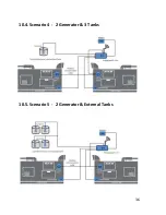
29
To install and commission for 3P4W, proceed the the following
instructions:
●
Push the unit into the panel and mount using the clamp.
●
Connect the auxiliary supply (85 AC to 265V AC) to the terminals
marked L and N.
●
Connect the three phases with the phase sequence being R-Y-B to
the terminals marked VR, VY and VB respectively. Make sure that
the phases coming to the unit come through control fuses of 2.0A
rating.
●
Connect the neutral wire to the terminal marked N.
●
Connect the two wires from the R-phase CT to the terminal
marked IR+ and IR- such that S1 from CT goes to IR+.
●
Connect the two wires from the Y-phase CT to the terminals
marked IY+ and IY- such that S1 from the CT goes to IY+.
●
Connect the two wires from the B-phase CT to the terminals
marked IB+ and IB- such that S1 from the CT goes to the terminal
marked IB+.
●
Switch on the auxiliary supply as well as three phase supply and
then, the unit will come live.
9.2.2 3 Phase 3 wire System
Fig 3 Connection Scheme 3 phase 2 wire Direct Connection using 2 CTs, 2 PTs
Содержание EnergyLogicIQ
Страница 1: ...2018 LogicLadder Instruction Manual EnergyLogicIQ Generator Monitoring System Version 12 2017...
Страница 2: ......
Страница 16: ...11...
Страница 17: ...12 7 EnergyLogicIQ IoT Cloud Connector A Top View B Top Side View...
Страница 18: ...13 C Left Side View D Bottom Side View...
Страница 24: ...19 7 8 Connecting Generator On Off Signal and Run Hours...
Страница 38: ...33 2 Setup communication parameter...
Страница 40: ...35 10 2 Scenario 2 1 Generator 2 Tanks 10 3 Scenario 3 2 Generator 2 Tanks Internal Tanks...
Страница 41: ...36 10 4 Scenario 4 2 Generator 3 Tanks 10 5 Scenario 5 2 Generator External Tanks...
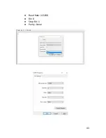
Страница 48: ...43 Baud Rate 115200 Bit 8 Stop Bit 1 Parity None...
Страница 50: ...45 13 Declaration of Conformity...
Страница 51: ...46...
Страница 52: ...47...
Страница 54: ......


