Page 6
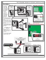
“X” Audio & Video Installation
Red = Audio Input +
Green = Audio Input -
LEFT Side of Speaker
RIGHT Side of Speaker
Installation
1) Separate back housing from
front housing. Step 1 Remove
set screw Step 2: swing bottom
of housing out. Step 3: pull back
housing out from top hinge. See
Fig-2
2) Knock out wiring hole. Feed
wire through opening
See Fig-3
Note: We recommend that you
use silicon sealer to protect the
wiring around the hole
3) Mount back box using desired
mounting hole knock outs and
secure firmly.
See Fig-3
4) Connect the two wires to the
wiring post on the inside of Door
Speaker. See Fig 4 and Fig 4.1
(Video Model: See Fig 4.2 for
video connection)
5) Mount front housing of Door
Speaker on the secured back
box. Secure front housing using
bottom set screw. See Fig-2.1
Steps 1, 2 & 3
12Volt -
Common Ground
Video
Red
Green
Fig 4
Video
Power
Supply
(supplied with
doorstation)
12V DC
Output
Ring On/Off Relay Contacts Door Spkr 2
Door Spkr 1
Tele Line In & Out
Power Plug
RJ11 Modular Wire
(Supplied with controller)
To
Speaker Jack
TeleDoorBell
RCA Patch Cord
(supplied with Speaker)
To Video input or Cable Modulator, DVR,
Monitor, or Television
Common
(GROUND)
12VDC +
Video +
Video -
Wire can vary from standard quad, CAT-5 and/or RG6 for the Video Signal. Speaker distance from controller is a factor and
should be considered.
VIDEO NOTE: Wire recommended for
most applications under 100 ft is CAT-5.
RG-6 Wire for video signal should be used
for longer distances.
Fig 3
Wiring Hole
Fig 2 (Side View)
1
2
VOLUME
MIN
MAX
IN-
IN+
VOLUME
MIN
MAX
+AUDIO
+VIDEO
COMMON GND-
+12V
VIDEO
Video
Out
Audio
Out
IN+
IN-
Audio
Audio
Fig 4.1
Fig 4.2
Inside of Door Speaker
Video and Audio terminals
Volume Control may need to be
adjusted to accommodate for
different acoustic environments.
+AUDIO
+VIDEO
COMMON GND-
+12V
VIDEO
VIDEO
AUDIO
12VDC -
Mounting Holes
Mounting Holes
Pre
Mounting
Box
Install
Fig 2.1 (Side View)
Post
Mounting
Back Box
Install
1
2
3
Set Screw


