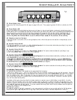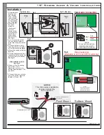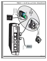
Controller Wiring Diagram
Page 8
Existing
doorbell
Transformer
120V AC
Already connected
OUT
OUT
IN
IN
Existing
doorbell switch
(to be removed)
Transformer
Front Door
Door Bell
Disconnect
switch and connect
wires together
Wire is reconnected
to the TeleDoorBell
Doorbell rewiring section
Red
Grey
Red
Yellow
Yellow
Black
Black
Green
Brown
Green
RJ31X
(CA38A)
Data Jack
16V AC
Output
To
Phone
TeleDoorBell
TM
Figure 5
Spk/Rly#1
Spk/Rly#2
Spk/Rly#3
Spk/Rly#4
Tele Line In & Out
Power Plug
A202CR & A204CR
Relay #1
connection
Relay #3
connection
#11
(to activate)
#31
(to activate or will automatically
activates if configured as the
DoorBell function)
Applicable
for both
A202 &
A204
Models
NOTICE
See Page 6 & 7 for
Door Station Connectivity.
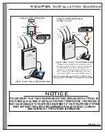
OUT
OUT
IN
IN
RJ31X
(CA38A)
Alarm Jack
LINE from phone provider,
VOIP Modem or Cable Modem
Alarm jack
connection
only if alarm
monitored
RELAY SPECIFICATIONS:
Normally Open Relays are rated for up to:
(1 Amps at 12-24 AC or DC Volts).
(1) Door station Included with
any kit purchase


