L o g a n G r a p h i c P r o d u c t s I n c . , 1 1 0 0 B r o w n S t r e e t , Wa u c o n d a , I L 6 0 0 8 4 To l l F r e e 1 8 0 0 3 3 1 6 2 3 2 w w w. l o g a n g r a p h i c . c o m
14
FRAMER'S
EDGE
MAT CUTTER
MODELS 650, 655 & 660
Bearing Removal & Replacement
To Install New Bearings
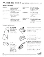
If the Cutting Head has sufficient wobble and the cut is hooking, the Delrin
bearings need replacement.
To Remove Old Bearings:
1. Remove the blades.
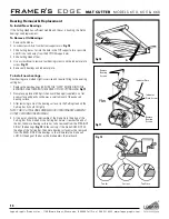
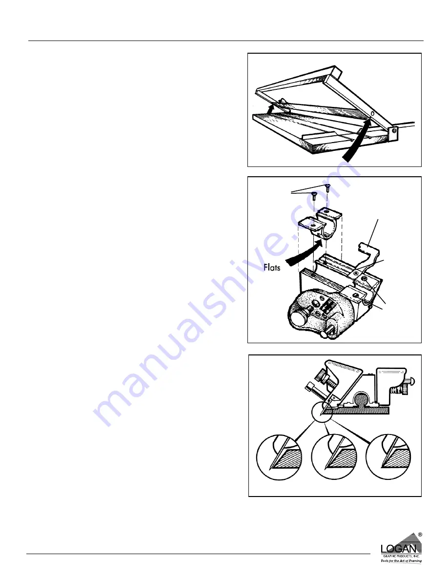
2. Loosen screws A & B from bottom support arms.
Fig 10
3. Slide Cutting Bar as far into the hole in the TOP support arm as possible
and lift it out and away from the BOTTOM support arm.
4. Slide Cutting Head off bar.
5. Use a screwdriver to remove four bearing screws and the indicator plate
screw.
Fig 11
6. Remove old bearings and indicator plate.
To install new bearings:
New bearings are molded slightly oversize and require fitting to the existing
cutting bar.
1. Replace the new bearings. BE SURE THE “FLATS” MOLDED INTO THE
BEARINGS FACE TOWARD THE CENTER OF THE CUTTING HEAD.
Fig 11
2. Now place a piece of 600 grit silicon carbide paper (supplied) on a flat,
even surface and gently sand away a small amount of the exposed
bearing surface.
3. After removing some of the bearing surface, try the Cutting Head on the
Cutting Bar. It should fit tightly.
NOTE: THIS IS A TRIAL AND ERROR METHOD OF BEARING REPLACEMENT.
DO NOT OVER-SAND THE BEARINGS.
4. At this point, check the relationship of the blade tip to the edge of the
Cutting Bar. If the blade hits the Cutting Bar before it reaches the end of
the bar, then more bearing surface has to be removed from the STRAIGHT
SIDE of the bearings.
Fig 12
On the contrary, if the blade DOES NOT hit
the edge of the Cutting Bar, then more bearing surface must be removed
from the BEVEL SIDE of the bearings so that ultimately the blade will
JUST hit the edge of the bar as the blade enters the matboard.
Fig 10
Fig 11
Indicator Plate
Indicator
Plate Screw
Remove
Bearing
Screws
Remove
Bearing
Screws
A
Too Far
Correct
Too Close
Fig 12
B


