5 HYDRAULIC INSTALLATION
24
▶
PLANT FILLING SYSTEM: if automatic filling systems are used, a seasonal check of the percentage of monoethylene glycol in the
plant is recommended.
For further information or technical support in this regard, contact Lochinvar.
The operations necessary for the First Activation or Regulation of the appliance must be carried out exclusively by an author-
ised Lochinvar Technical Assistance Centre (TAC). These operations are described in Section 7 p. 54).
The products' guarantee is void if initial activation is not carried out by a Lochinvar TAC.
5�4 GAS SUPPLY
The installation of gas supply pipes must be compliant with current regulations and norms.
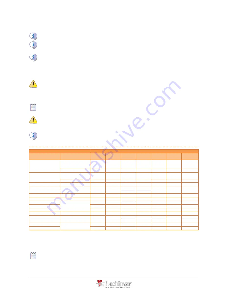
The gas supply pressure must be in the range given in Table 5.2 p. 24.
Supplying gas to the appliance at pressures higher than those indicated above can damage the gas valve, resulting in dan-
gerous situations.
LPG systems must be equipped with a first stage pressure reducer close to the LPG storage tank, in order to reduce the gas pressure
to 1,5 bar, and a second stage pressure reducer, close to the unit, in order to reduce pression from 1,5 bar to the value in agreement
with the gas network pressure of the country of installation (see Table 5.2 p. 24).
Exemple for the Italian market: for the G30 gas, from 1,5 bar to 0,030 bar (30mbar); for the G31 gas, from 1,5 bar to 0,037 bar
(37mbar).
LPG may cause corrosion; piping and fitting materials must be resistant to this corrosion.
Vertical gas pipes must be equipped with a siphon and provided with a drain for the con densate that may form inside the pipe dur-
ing cold periods. It may also be necessary to insulate the gas pipe to prevent the formation of excessive condensate.
In any case, provide an isolation valve (ball valve) on the gas supply line, to isolate the appliance when required.
Table 5�2 – Network gas pressure
Gas supply pressure
Product categories
Countries of destination
G20 [mbar]
G25 [mbar]
G30 [mbar]
G31 [mbar]
G25�1
[mbar]
G27 [mbar] G2,350 [mbar]
II
2H3B/P
AL, BG, CY, CZ, DK, EE, FI, GR,
HR, IT, LT, MK, NO, RO, SE,
SI, SK, TR
20
30
30
AT, CH
20
50
50
II
2H3P
AL, BG, CZ, ES, GB, HR, IE, IT,
LT, MK, PT, SI, SK, TR
20
37
RO
20
30
II
2ELL3B/P
DE
20
20
50
50
II
2Esi3P
FR
20
25
37
II
2HS3B/P
HU
25
30
30
25
II
2E3P
LU
20
50
II
2L3B/P
NL
25
50
50
II
2E3B/P
PL
20
37
37
II
2ELwLs3B/P
20
37
37
20
13
II
2ELwLs3P
20
37
20
13
I
2E(S); I3P
BE
20
25
37
I
3P
IS
30
I
2H
LV
20
I
3B/P
MT
30
30
I
3B
30
For data regarding hourly fuel consumption of the appliance, refer to Table 3.1 p. 9 or Table 3.2 p. 10.
5�5 CONDENSATE DISCHARGE
The fumes condensate outlet is on the left of the appliance.
The distance L between the coupling C and the base may not exceed 110 mm.
1.
The condensate discharge corrugated pipe, coming out from the side of the underbase left support, must be connected to a
proper discharge header.
2.
The connection between the pipe and the manifold must remain visible.
Содержание LCGHP
Страница 32: ...6 ELECTRICAL INSTALLATION 32 Figure 6 4 CCI DDC...
Страница 67: ......


