LMI Technologies Liquitron DC4000 Series Скачать руководство пользователя страница 36

38


If the probe reading is off by more than 50%, then the controller will indicate an error by displaying ‘CAL LIM µS‘.  
This generally means that the probe has failed or needs cleaning.

Alternately, a sample of cooling tower water may be analyzed by a precalibrated conductivity monitor, and the DC4000 

controller calibrated to match that reading using the sample as a standard solution.   

The DC4000 Controller provides a circuit board test-switch to aid in troubleshooting the unit and system.  The switch 

is located under the access cover on the lower section of the controller (see Figure 10). 

The conductivity test-switch allows the user to determine if the conductivity circuit is operating correctly.  When placed 

in the test position, this switch switches the conductivity probe and wiring out of the circuit and places an internal preci-

sion resistor.  This resistor has a known conductivity reading of 3000 µS +/- 5%. If the unit has been calibrated then this 

reading could be displayed as  + or - 50% of this 3000 µS value (+4500 µS, -1500 µS).
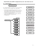
COND :  ( 

µS)3400

CAL:  ( µS)     3400

From Conductivity Screen....press Enter....to Calibrate


  In Calibration....

1)   press  

  or  

   to adjust conductivity reading value

2)   press          to save calibrated conductivity value

Figure 10:  Test Switch

ENTER

ENTER

(866) 433-6682 • (281) 359-8538 • [email protected] • www.novatech-usa.com

Содержание Liquitron DC4000 Series

Страница 1: ...Date Installation Location When ordering replacement parts for your LMI Controller or accessory please include the complete Model Number and Serial Number of your unit 201 Ivyland Road Ivyland PA 1897...

Страница 2: ...t Up Work Sheet 32 4 3 Boiler Installation 32 4 4 Determining the Blowdown Requirement 32 4 5 Timed Sampling Mode 33 4 6 Continuous Sampling 33 4 7 Boiler Installation Notes 33 4 8 Boiler Start Up 34...

Страница 3: ...condition exists flow switch must be installed The display is a 16 character backlit LCD liquid crystal display which is visible in all light conditions A three key position membrane is used to enter...

Страница 4: ...utput pigtails to allow for simple installation The unit can be hardwired through conduit to the lower junction box portion of the enclosure when required Hard wiring makes the unit suitable for NEMA...

Страница 5: ...le temperature is 122 F 50 C This should be considered if installation is in a high temperature location Once the DC4000 is wall mounted the metering pumps may be located at any distance from the cont...

Страница 6: ...mpensated cooling tower mode conductivity probe The DC4000 controller is provided with a voltage selector switch to allow the unit to be used with a 115 VAC or 230 VAC power source To change the volta...

Страница 7: ...for the connections required AC Power Input Hot TB4 1 Neutral TB4 2 Ground TB4 3 Bleed Blowdown Control Relay Output Hot N O TB3 1 Hot N C TB3 2 Neutral TB3 4 Ground To ground wire twist connect or G...

Страница 8: ...e N O or N C configuration The electrical wiring inputs are reversible since the flow switch connection has no polarity TB9 3 TB9 4 Thermistor Probe Input If Hardwiring Cooling Tower Probe Run the the...

Страница 9: ...and Wiring Diagram for Accessories Wiring diagram for Boiler Applications with 1 2 Conduit connections Dotted lines represent HARDWIRED Accesories DC4000 866 433 6682 281 359 8538 sales novatech usa...

Страница 10: ...and Wiring Diagram for Accessories Wiring diagram for Boiler Applications with 1 2 Conduit connections Dotted lines represent HARDWIRED Accesories DC4000 866 433 6682 281 359 8538 sales novatech usa...

Страница 11: ...tructions below for the connections required AC Power Input Hot TB2 1 Neutral TB2 3 Ground TB4 1 Bleed Blowdown Control Relay Output Hot N O TB5 1 Hot N C TB5 2 Neutral TB1 1 Ground To ground wire twi...

Страница 12: ...guration The electrical wiring inputs are reversible since the flow switch connection has no polarity TB10 3 TB10 4 Thermistor Probe Input If Hardwiring Cooling Tower Probe Run the thermistor probe wi...

Страница 13: ...nal Strip Layout and Wiring Diagram for Accessories Wiring Diagram for version only Dotted lines represent HARDWIRED Accessories CE DC4000 866 433 6682 281 359 8538 sales novatech usa com www novatech...

Страница 14: ...r reviewing or changing the conductivity controller programming setpoints the unit must be returned to the System Run or conductivity reading screen to allow automatic control to proceed There are thr...

Страница 15: ...dow to another line item When not in the System Run mode the outputs to the control relays are disabled The following is the order of items in the main menu CONDUCTIVITY SET POINT DIFFERENTIAL LOW ALA...

Страница 16: ...ys can be pressed to change the conductivity reading and adjust for inaccuracies If calibration adjustment is attempted beyond 50 of the probe conductivity reading the controller will flash a warning...

Страница 17: ...ing ENTER from the main menu SET POINT screen accesses the conductivity reading trip value and allows the value to be changed The value will have a flashing cursor indicating that it can be changed Pr...

Страница 18: ...he trip SET POINT that the bleed relay will shut off Press ENTER from this screen to change the value The value will have a flashing cursor indicating that it can be changed Press the UP or DOWN key t...

Страница 19: ...have a flashing cursor indicating that the value can be changed Press the UP or DOWN key to increase or decrease the setting Press ENTER to save the value LO ALARM 250 Low Conductivity Alarm Set Point...

Страница 20: ...l have a flashing cursor indicating that the value can be changed Press the UP or DOWN key to increase or decrease the setting Press ENTER to save the value HI ALARM 4000 High Conductivity Alarm Set P...

Страница 21: ...gh the four different modes When the mode desired is displayed on the screen press ENTER to ac cess the particular settings for that mode The variables and settings that are available for each option...

Страница 22: ...ond time to de energize that relay One or all of the relays may be energized in this manner The output relays will be de energized if 1 No keys are pressed for 3 minutes and the controller returns to...

Страница 23: ...ogic TRIP bleed based on either rising or falling conductivity trip point 4 20 mA recorder output programming Conductivity units DISPLAY may be either Siemens or PPM TDS BLEED control Boiler or Coolin...

Страница 24: ...ressing the UP or DOWN key toggles between displaying F or C Pressing ENTER a second time saves the displayed Temperature selection Temperature will not be displayed in the Boiler mode Default Tempera...

Страница 25: ...set of the totalizer back to zero The maximum accumulation is 65 000 gallons liters TOTAL 00000 GAL TOTAL 00000 GAL Use or key to select RATIO or RESET Water Meter Totalizer Screen ENTER ENTER ENTER C...

Страница 26: ...he BOILER screen will appear in the MAIN menu Navigate to this screen BOILER Use or to toggle from CONTINUOUS or TIMED conductivity sampling Press to select that mode If CONTINUOUS sampling is selecte...

Страница 27: ...e programmed TRAP TIME At the end of the TRAP TIME the control then reads the conductivity and reacts on it This delay or TRAP TIME allows any flashed boiler water or steam to be re compressed This el...

Страница 28: ...and that the probe is fully emersed This prevents the electrode from becoming air bound System shut off isolation valves are recommended for installation on either side of the conductivity sensing ele...

Страница 29: ...be used to select falling trip point for closed loop systems or to select the boiler mode 4 2 Pre Start Up Work Sheet Pre Start Up Work Sheet 1 Current system conductivity in S 2 Desired conductivity...

Страница 30: ...e to use is important As a rule of thumb if the blowdown requirement of the boiler is greater than 5000 lbs hr the boiler may be continuously sampled Since the boiler sample is sent to drain and not r...

Страница 31: ...point the controller will start another Off Time cycle If the conductivity is above the set point the controller will conduct another blow down or Duration cycle time 4 6 Continuous Sampling For large...

Страница 32: ...nformation in this manual 4 9 Timed Sample Start Up 1 Check that the unit is installed as shown in Figure 7 Timed Sample on page 30 2 Complete the Pre Start Up Work Sheet on page 26 3 Supply power to...

Страница 33: ...35 Figure 7 Timed Sample Figure 8 Continuous Sample 866 433 6682 281 359 8538 sales novatech usa com www novatech usa com...

Страница 34: ...for control of chemical levels in closed loop systems Unlike cooling towers and boilers that respond to a rising conductivity set point to control bleed off the closed loop mode enables the unit to r...

Страница 35: ...a discrepancy exists between the displayed conductivity value and the conductivity value determined by a reliable alternative such as an accurate hand held tester 1 Check that the conductivity probe...

Страница 36: ...of the controller see Figure 10 The conductivity test switch allows the user to determine if the conductivity circuit is operating correctly When placed in the test position this switch switches the c...

Страница 37: ...tion as shown in Figure 11 The probe should be cleaned parallel to the carbon electrodes NOT perpendicular Figure 11 Frequency The probe should periodically be cleaned to maintain accurate measurement...

Страница 38: ...ing to valve Check wiring by using Relay Test program Valve has failed Test per manufacturers instructions Incorrect Blowdown setpoint Verify setpoint and rising falling trip selection Low Conductivit...

Страница 39: ...m Relay 1 250 VAC 10 amp contact relay Contact type Normally open and normally closed contacts FORM C Change over relay LCD Display 16 Digit Liquid Crystal Display LCD with green backlighting Operatin...

Страница 40: ...42 10 0 Product Exploded View 866 433 6682 281 359 8538 sales novatech usa com www novatech usa com...

Страница 41: ...17 31617 Cover Liquitron 18 32094 Label Housing cover LMI 19 32211 Cap 125 x 38 20 32352 O Ring Sponge 21 32395 Screw Self Tapping 22 34911 Cover Fuse 23 32635 Terminal Grounding 24 34915 Standoff He...

Страница 42: ...12 0 Statement of Limited Warranty LMI TERMS AND CONDITIONS OF SALE Visit the LMI web site at www lmipumps com for warranty details 866 433 6682 281 359 8538 sales novatech usa com www novatech usa c...

Страница 43: ...ut notice Liquitron is a trademark of Milton Roy LLC 201 Ivyland Road Ivyland PA 18974 USA TOLL FREE 800 564 1097 TEL 215 293 0401 FAX 215 293 0445 http www Imipumps com sales novatech usa com www nov...

Отзывы: