


32
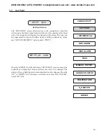
Once the operating settings and parameters have been determined by the data entered above, the DC4000 Controller can
then be programmed. Supply power to the controller. Read the conductivity and verify the accuracy using a calibrated
meter and conductivity sample. Calibrate the controller as needed. See Calibration section.
In the Main Menu, enter the required values for Conductivity, Differential, Low Alarm and High Alarm/.
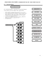
Go to the FEED menu screen (see FEED programming sheet in manual) and enter the required mode and
settings for the chemical inhibitor pump control.
Go to the SET UP menu screen (see SET UP programming sheet in manual) and enter the Flow Alarm
Option, Trip Actuation, 4 - 20 mA settings, Display Mode, and Control Cooling Tower/Boiler Mode.
Use the MANUAL OUTPUTS menu (see MANUAL OUTPUTS programming sheet in manual) to check that
all controlled devices are properly connected.
This completes the cooling tower start-up. Return the display to the ‘SYSTEM RUN’ or ‘CONDUCTIVITY
Reading
’
screen to begin operation.
The system will return to the ‘SYSTEM RUN’ mode automatically on its own after three (3) minutes
if no keys are pressed.
4.3 Boiler Installation
The DC4000 controller when used for boiler conductivity control can be set up in two different operating modes:
•
Timed sampling
• Continuous sampling
The choice of which mode to use is important. As a rule of thumb, if the blowdown requirement of the boiler is greater
than 5000 lbs/hr, the boiler may be continuously sampled. Since the boiler sample is sent to drain and not returned to the
system, continuously sampling a smaller (less than 5000 lbs/hr blowdown requirement) boiler can result in excessive
blowdown.
Timed sampling is the best mode to select when the blowdown requirement will be less than 5000 lbs/hr. The controller
allows only periodic samples of boiler water to pass the electrode. If the sample is high in conductivity, the sampling
period will extend until the conductivity falls below preset levels. Once the conductivity is below the set point, including
differential, the periodic sampling will resume at the preset intervals.
4.4 Determining the Blowdown Requirement
If the blowdown requirement for your particular boiler is unknown, it can be approximated by knowing the following
data and applying the formula below:
Data Required
H.P. = Boiler Horsepower
% Condensate = % of Condensate Return to Boiler
Cycles = Cycles of Concentration
Formula
a. H.P.
x
34.5 = Steam Output (lbs./hr)
b. Steam Output (lbs/hr)
x
(1 -
) = Make-Up Req. (lbs/hr)
c. Make-Up Req. (lbs/hr)
x
(
) = Blowdown Req. (lbs/hr)
Example
A 200 horsepower boiler returning 50% condensate operating at 4 cycles of concentration.
a. 200 H.P.
x
34.5 = 6,900 lbs/hr Steam Output
b. 6,900 lbs/hr
x
( 1-
) = 3,450 lbs/hr Make-Up Req.
c. 3,450
x
(
) = 1,150 lbs/hr Blowdown Req.
1
Cycles - 1
50
%
4-1
1
Condensate
100%
100%
(866) 433-6682 • (281) 359-8538 • [email protected] • www.novatech-usa.com


