


36
4.10 Continuous Sample Start-Up
1. Check that the unit is installed as shown in Figure 8 Continuous Sample on page 30.
2. Complete the Pre-Start-Up Work Sheet on page 26.
3. Supply power to the DC4000 controller, read the conductivity and verify accuracy using a calibrated
meter and sample. Calibrate as needed.
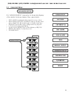
4. Go to the
Set-Point
screen and enter the desired conductivity set point.
5. Go to the Differential screen and enter the desired deadband.
6. Go to the High and Low Alarm screens and enter the desired values.
7. Go to the
Feed
screen and press . Use the and keys to move to the type of feed
desired. Press to select that mode. Use the and keys to set the correct feed times or
percentages for your application. Press to save that setting. Now the feed screen will display
with the feed mode you selected.
8. Use the
Test
menu to check all controlled devices (i.e. pumps, valves, alarm devices) are properly
connected. See test section for directions.
9. Return the unit to the Conductivity “System Run” screen. This completes the start-up sequence for
continuous sampling boiler operation.
4.11 Closed Loop Installation Theory of Operation
The DC4000 can be configured with a reverse or falling set point to allow for control of chemical levels in closed loop
systems. Unlike cooling towers and boilers that respond to a rising conductivity set point to control bleed off, the closed
loop mode enables the unit to respond to a falling set point to control chemical feed.
The DC4000 is installed to monitor the system conductivity. Whenever the conductivity drops due to the addition of
make-up water, the DC4000 will turn on a chemical feed pump which will cause the conductivity to rise. When the
conductivity returns to the proper level (set point plus differential) the chemical feed pump will shut down, and wait for
the addition of more make-up water.
4.12 Closed Loop Start-Up
1. Check that the unit is installed as shown in Figure 9 on page 32.
2. Complete the Pre-Start-Up Work Sheet on page 26.
3. Supply power to the DC4000 controller. Read the conductivity and verify accuracy. Calibrate as
needed.
4. The Bleed or Control Output is now used to power a pump.
5. Go to the
Set Point
screen and enter desired pump (bleed) energizing value.
6. Generally no differential or deadband is used: none is required for a pump. Program High / Low
Alarm as desired.
7. The Manual Outputs menu screen should be used to test outputs.
8. Return the unit to the Conductivity screen or “System Run” . This completes the start-up sequence for
closed loop operation.
ENTER
ENTER
ENTER
(866) 433-6682 • (281) 359-8538 • [email protected] • www.novatech-usa.com


