background image


40 

hold larger work than the same size 3-jaw chuck. You can offset work in a 4-
jaw chuck by clamping it off center.  

LittleMachineShop.com part number 
1588

4" 4-jaw chuck. Each jaw is 

independently adjustable and 
reversible.  
This set includes a chuck key and 
reversible jaws. The through bore of 
this chuck is 0.98". The chuck can 
hold work up to 100 mm (3.94") in 
diameter. 

LittleMachineShop.com part number 
2338

5" 4-jaw chuck. This chuck has 

a through bore of 1.18" and can hold work up to 125 mm (4.92") in diameter. To 
mount a 5" chuck on the HiTorque Mini Lathe, you

ll need an adapter 

(

LittleMachineShop.com part number 2961

). 

Faceplate 

A faceplate allows you to mount work that can’t be held in a chuck. You can 

bolt odd-shaped workpieces to the faceplate. 


LittleMachineShop.com part number 5123

Faceplate for the HiTorque Mini Lathe. 
The faceplate is 6.29" (160 mm) in 
diameter and has 8 slots for mounting 
work. 

LittleMachineShop.com part number 2644

Clamping kit for faceplate. This kit 
includes clamping bars and fasteners to 
attach work to the faceplate. 

Centers and Dogs 

A live center goes in the tailstock and is used to support the end of a long 
workpiece; it rotates with the workpiece. A dead center goes in the spindle 
and supports work being turned between two centers. A lathe dog is used to 
drive work being turned between centers.  

Содержание HiTorque 5100

Страница 1: ...The premier source of tooling parts and accessories for bench top machinists HiTorque 7x16 Mini Lathe Users Guide Model 5100 Model 7350 Deluxe from LittleMachineShop com ...

Страница 2: ...ed Photos Copyright 2019 PhotoBoost com All rights reserved Written by Chris Wood of LittleMachineShop com Revision 2 August 2019 LittleMachineShop com https www littlemachineshop com 396 W Washington Blvd 500 Pasadena CA 91103 800 981 9663 Fax 626 584 5844 ...

Страница 3: ...e Lever 12 Power Feed Lever 12 Carriage Hand Wheel 12 Cross Slide Feed Handle 13 Compound Rest Feed Handle 13 Digital Position Readout Model 7350 only 13 Compound Rest Rotation 14 Tailstock Locking Lever 15 Tailstock Quill Hand Wheel 15 Tailstock Quill Digital Position Readout Model 7350 only 15 Tailstock Quill Locking Lever 15 Adjustments 15 Carriage 16 Cross Slide Gibs 16 Cross Slide Nut 17 Comp...

Страница 4: ...Height 27 Turning 27 Manual Turning 27 Turning with Power Feed 28 Facing 29 Turning Angles 30 Cutting Threads 30 Change Gears 31 Threading Dial 34 Tool Bit 35 Compound Angle 36 Setting the Cutting Tool 36 Threading Process 37 Common Accessories 38 Cut Off Tool Holder 38 Quick Change Tool Post 38 Indexable Turning Tools 39 4 Jaw Chuck 39 Faceplate 40 Centers and Dogs 40 Steady Rest and Follower Res...

Страница 5: ...athe with the following kits available from LittleMachineShop com Part number 5675 Digital Position Readout 2 Axis Mini Lathe Part number 5879 Digital Position Readout Mini Lathe Tailstock Part number 3937 Knob and Hand Wheel Kit Part number 3112 Quick Change Tool Post Set 0XA Mini Lathe Installation of all four kits creates a machine that is functionally identical to a Model 7350 deluxe lathe Spe...

Страница 6: ...fter you place it in the chuck or other work holding device Be sure it is secure before turning on the lathe Don t wear loose clothing or jewelry when operating the lathe Stop the spindle and make sure the machine is in a safe condition before o Opening or removing safety shields o Reaching into work area o Changing or adjusting tools o Changing or adjusting workpieces o Changing speed ranges o Cl...

Страница 7: ... side shields are recommended that are ANSI Z87 1 2003 compliant Wear hearing protection ear plugs or ear muffs when operating loud machines Wear appropriate clothing no rings gloves neckties jewelry or loose fitting garments Bind long hair or wear a hat Do not use compressed air for cleaning machines A shop vacuum works well and is much safer Don t operate machinery while under the influence of d...

Страница 8: ... for example are flammable Understand the materials you are using Features Front View 1 Motor controls 2 Headstock 3 3 jaw chuck 4 Carriage 5 Cross slide 6 Tool post 7 Compound rest 8 Compound rest feed handle 9 Tailstock quill 10 Tailstock quill locking lever 11 Tailstock locking lever 12 Tailstock quill hand wheel 13 Change gear cover 14 Carriage hand wheel 15 Apron 16 Cross slide feed handle 17...

Страница 9: ... Lathe Chuck key for the 3 jaw chuck Outside jaws for the 3 jaw chuck Change gears 21 30 35 40 2 45 50 55 57 60 and 65 teeth Hex wrenches 3 4 5 and 6 mm Open end wrenches 8 x 10 mm and 14 x 17 mm 2 Morse taper dead center Oil can plastic Power feed forward neutral reverse lever ...

Страница 10: ... socket head cap screws that are furnished Instead of installing the mounting feet you may wish to mount your lathe to a bench as described in the next section Mounting Your Lathe The HiTorque Mini Lathe comes with rubber feet and spreader bars that attach to the same holes used to secure the lathe for shipping If you want your lathe to be portable simply install these spreader bars and feet You c...

Страница 11: ... button To turn the switch on press the green button The power switch interrupts the input power to the speed control circuit board The forward off reverse switch switches the polarity of the speed control circuit board output power between the speed control circuit board and the motor You control the motor speed by adjusting a potentiometer that provides the speed setting value to the speed contr...

Страница 12: ...is lever is in the forward or top position the lead screw moves the carriage toward the headstock When this lever is in the reverse or bottom position the lead screw moves the carriage away from the headstock In the center or neutral position the lead screw is disengaged and does not turn There is a strong spring in this lever Pull out firmly on the end of the lever while moving it Power Feed Leve...

Страница 13: ...0 03937 an error of a little less than 2 Compound Rest Feed Handle The compound rest feed handle advances or retracts the compound rest Use this handle to advance the tool into the work The dial on this handle indicates the relative position of the compound rest The graduated dial can be repositioned for convenience There are 40 divisions on the dial Each turn of the handle advances the compound r...

Страница 14: ...eadings when you are turning the screw in the same direction This is not a problem on a lathe because a single cut will only be made in one direction in for turning and out for boring To replace the battery Each DRO uses a single CR2032 lithium battery LittleMachineShop com part number 4292 1 On the bottom of the display unit squeeze together the two tabs and then pull out the battery drawer 2 Rep...

Страница 15: ...taper in the tailstock quill Tailstock Quill Digital Position Readout Model 7350 only The HiTorque 7 16 Deluxe Mini Lathe has a digital readout on the tailstock that displays the quill position more precisely than the graduated markings on the standard model Operation of the tailstock readout is the same as those for the compound rest and cross slide See Digital Position Readout Model 7350 only on...

Страница 16: ...s through the front of the carriage 3 Slide the apron to the right and off the lead screw 4 Loosen all the fasteners on both retainers 5 Snug the socket head cap screws so the carriage can move but without play 6 Snug the setscrews Do not over tighten or you might break the retainers 7 While holding the setscrews from turning tighten the lock nuts 8 Replace the apron 9 Replace the right lead screw...

Страница 17: ...ip the nut off horizontal to reduce the endplay in the threads The center screw locks the adjustment in place To adjust the cross slide nut 1 Loosen all three screws 2 Tighten the outside setscrews until you just start to feel resistance turning the set screw 3 Loosen the near set screw and tightened the center screw until you just start to feel resistance turning the cap crew At this point the bo...

Страница 18: ...en the lock nuts 6 Test by turning the handle Loosen or tighten all the setscrews the same amount until the compound rest moves freely but without play in the dovetail Apron Position The apron is adjustable to center the half nuts horizontally on the lead screw To adjust the apron position 1 Loosen the two socket head cap screws that secure the apron to the carriage They are at the front edge of t...

Страница 19: ...e horizontal and the width vertical Bring the centers together to hold the rule in place 11 Adjust the upper part of the tailstock casting until the steel rule is perpendicular to the axis of the lathe If the near end of the rule angles toward the headstock move the tailstock back 12 When the tailstock is in the correct position tighten the tailstock adjustment setscrews 13 Gently remove the tails...

Страница 20: ...he end of the ways 2 Loosen the two mounting socket head cap screws on the right bracket 3 Move the carriage as far to the right as possible 4 Engage the half nuts on the lead screw 5 Tighten the bracket mounting socket head cap screws 6 Replace the tailstock To adjust the left lead screw mounting bracket 1 Remove the change gear cover 2 Loosen the locking nut on the change gear adjuster 3 Loosen ...

Страница 21: ...ing The maintenance you perform most often is cleaning Keeping swarf chips shavings and debris off of wearing surfaces is the most important thing you can do to prolong the life of your mini lathe Use a 1 paintbrush to remove swarf from the ways as you work Clean the lead screw before each use Clean swarf from the lathe from top down after each use Lubrication We recommend the use of two lubricant...

Страница 22: ...d screw threads Oil Daily Clean swarf chips shavings and debris daily Compound rest dovetail Oil Daily Advance the compound rest to the extent of its normal travel Apply oil to the end of the gib and the ends of the dovetails Retract the compound rest Cross slide dovetail Oil Daily Advance the cross slide to the extent of its travel Apply oil to the end of the gib and the ends of the dovetails Ret...

Страница 23: ...use the stepped side is designed to fit inside of hollow workpieces and hold by an outward force In many cases however these jaws are used to clamp on the outside of smaller objects using the long straight side The second set of jaws is called the outside jaws because the stepped side of these jaws is designed to clamp on the outside of larger objects Because of the construction of a 3 jaw chuck e...

Страница 24: ...uck Mounting Work in a 3 Jaw Chuck Three jaw lathe chucks are good for most lathe operations All three jaws move together as you turn the chuck key But because of the way they are made 3 jaw chucks have limited accuracy They will center work to within about 0 003 runout If you need better concentricity use an independent 4 jaw chuck or a collet If you chuck a workpiece create a part and then part ...

Страница 25: ...e cutting edge does most of the cutting As the tool bit moves along the workpiece the side cutting edge removes most of the material Front cutting edge The front cutting edge cuts when the tool is advanced into the work Nose The nose is a critical part of the cutting edge because it produces the surface finish of the workpiece Side rake The side rake produces the side cutting edge that cuts into t...

Страница 26: ...elief The first step in creating a tool bit is to grind the front relief For most work a relief angle of 10 works well While you are grinding the front relief you are also creating the front cutting edge angle Make this angle about 10 also so that the corner formed by the front cutting edge and the side cutting edge is less than 90 Grind the Left Side Relief Form the left side relief next Again cr...

Страница 27: ...ing shims under the tool bit You can get an economical set of shims about the right size at any auto parts store Purchase a set of feeler gages and remove the pivot pin The easy way to adjust the tool bit height is to get a quick change tool post Model 7350 includes a quick change tool post set Virtually all quick change tool posts incorporate a mechanism for easily adjusting the tool bit height T...

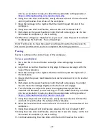
Страница 28: ...ini lathe incorporates a power carriage feed that can move the carriage either direction This same power feed is used for turning and threading For turning the change gear train is configured with 20 tooth gears in positions A and C and 80 tooth gears in positions B and D This is the way the lathe comes from the factory and is how you should reset it after threading If you haven t changed the gear...

Страница 29: ...e the tool so that the side cutting edge forms an acute angle with the face of the workpiece 3 Move the carriage to the right so that the tool bit is past the right end of the workpiece 4 Ensure that the power feed forward neutral reverse lever is in the neutral position 5 Push down on the power feed lever until the half nuts engage You might have to move the carriage slightly so the half nuts wil...

Страница 30: ... use the same method for small angles usually called tapers of a length less than the compound rest travel For longer tapers the work is usually placed between centers with the tail center offset from the centerline of the lathe Cutting Threads Much of the mechanism of your lathe is provided to allow you to cut threads Your lathe can cut a broad range of thread pitches In fact with the standard ch...

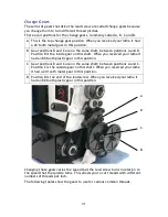
Страница 31: ...you received your lathe it had an 80 tooth plastic gear in this position C Gear positions B and C are on the same shaft between positions A and C Position C is the outside gear on this shaft When you received your lathe it had a 20 tooth metal gear in this position D Position D is the end of the lead screw When you received your lathe it had an 80 tooth plastic gear in this position Changing these...

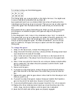
Страница 32: ...4 20 Any gear 55 48 40 60 40 80 56 40 35 20 80 64 20 Any gear 80 72 40 45 20 80 80 20 80 40 50 American Standard Metric Threads Pitch mm A B C D 0 3 20 57 35 65 0 35 20 80 50 57 0 4 20 55 45 65 0 45 20 60 55 65 0 5 21 50 45 60 0 6 21 50 45 50 0 7 35 55 45 65 0 75 35 65 50 57 0 8 40 65 45 55 1 21 50 60 40 1 25 35 40 45 50 1 5 40 50 65 55 1 75 40 35 55 57 2 40 50 55 35 2 5 60 55 65 45 3 65 55 80 50 ...

Страница 33: ...ars 1 Using a 4 mm hex wrench remove the change gear cover 2 Using 4 mm and 5 mm hex wrenches remove all three retaining socket head cap screws from the ends of the shafts 3 Use a 10 mm end wrench to loosen the nut that is on the back end of the shaft in position B C This allows the B C shaft to move in the adjustment slot 4 Use a 14 mm end wrench to loosen the nut on the arc below and behind the ...

Страница 34: ... gear on the threading dial has 16 teeth and the lead screw has 16 threads per inch so each revolution of the threading dial represents one inch of motion of the carriage Each of the eight divisions on the dial represents 1 8 of motion Chris Tip You simply can not use the threading dial when cutting metric threads Leave the lead screw engaged all the time When you are done with a pass note the pos...

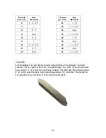
Страница 35: ...5 7 48 Any 52 1 3 5 7 Tool Bit For threading the tool bit is ground to the profile of the thread For most threads this is a point with a 60 included angle The front of the tool should have about 10 of relief No back rake is used The left side should have about 8 of relief and the right side should have about 10 of relief The tip of the tool should have a flat that is 1 8 of the thread pitch ...

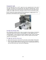
Страница 36: ...the Cutting Tool Even though the compound rest is set at an angle to the workpiece the thread cutting tool must be set square to the workpiece A center gage makes this setting possible A center gage has several V shaped cutouts They can be used to check the tool bit as you grind it and to check the angle of the tool with respect to the workpiece To align the tool bit to the work 1 Ensure that the ...

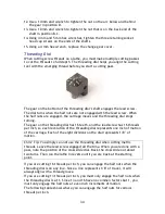
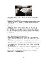
Страница 37: ... away from the head stock to cut left hand threads For each pass in cutting threads 1 Move the carriage to the beginning of the cut 2 Advance the cross slide to the initial position For the first pass you are already there For additional passes advance it 2 complete turns to the 0 mark 3 Advance the compound rest to move the tool bit into the work For the first pass this should be only 0 001 For a...

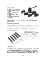
Страница 38: ...ich means they will not fit in the tool post that comes with the mini lathe The cut off tool holder shown below fits in the standard tool post and holds a tall cut off blade LittleMachineShop com part number 1551 This cut off tool holder fits in the standard 4 way tool post and most other tool posts and holds 1 2 tall cut off blades Quick Change Tool Post The standard mini lathe tool post has posi...

Страница 39: ...use you can change an insert and the new insert will take the exact position of the insert it replaces You can resume work with no further adjustments Indexable inserts are pre sharpened LittleMachineShop com part number 1669 This set of indexable turning tools includes 5 tools AR AL BR BL TE wrenches and extra screws It comes in a fitted case The letters designate the angles of the cutting edge 4...

Страница 40: ...d an adapter LittleMachineShop com part number 2961 Faceplate A faceplate allows you to mount work that can t be held in a chuck You can bolt odd shaped workpieces to the faceplate LittleMachineShop com part number 5123 Faceplate for the HiTorque Mini Lathe The faceplate is 6 29 160 mm in diameter and has 8 slots for mounting work LittleMachineShop com part number 2644 Clamping kit for faceplate T...

Страница 41: ...umber 4464 This lathe dog set can handle work up to 1 5 40 mm Steady Rest and Follower Rest Steady and follower rests support small diameter work that would otherwise flex too much A steady rest mounts in a fixed position on the ways of the lathe A follower rest mounts on the carriage and moves with the cutting tool providing support where it is needed The steady rest is LittleMachineShop com part...

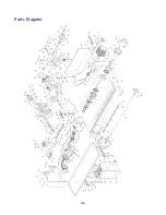
Страница 42: ...42 Parts Diagram ...

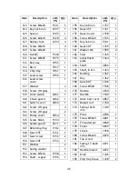
Страница 43: ...5 4 26 Screw M5x10 1569 5 27 Nut M4 6 28 Screw M4x16 1568 3 29 Screw M4x8 1531 2 Item Description LMS PN Qty 30 Screw M4x12 1530 4 31 Washer M8 1586 2 32 Lock washer M6 2176 2 33 Screw M6x10 4 34 Screw M8x20 1544 2 35 Saddle 1389 1 36 Saddle retainer 1388 2 37 Cross slide 1286 1 38 Feed screw cross slide 1387 1 39 Gib cross slide 1108 1 40 Nut cross slide 1203 1 41 Retainer 1386 1 42 Dial imperial...

Страница 44: ...33 1 88 Screw M5x25 1 89 Hub 4050 1 90 Connector 4051 1 91 Screw M6x14 1 92 Screw M8x40 1579 1 Item Description LMS PN Qty 93 Tailstock casting 1996 1 94 Tailstock base 1996 1 95 Foot 4052 1 96 Washer 1 97 Tailstock screw 1304 1 98 Retainer 1305 1 99 Quill 1306 1 100 Handle 1309 1 101 Clamp 1308 1 102 Control box 4053 1 103 Switch label 4054 1 104 Switch 4055 1 105 Jack 4056 1 106 Fuse 3797 1 107 ...

Страница 45: ...w 1352 2 150 Gear 20T 1353 1 151 Washer 2 152 Spring washer 1 153 Screw M5x10 1558 1 154 Shaft A gear 1356 1 Item Description LMS PN Qty 155 Key 3x8 mm 1357 1 156 Gear 45T 1321 1 157 Gear mount 1358 1 158 Screw M5x20 1535 2 159 Key 3x6 mm 5341 1 160 Gear 20T 1359 2 161 Washer M6 1585 2 162 Stud 1365 1 163 Adjustment plate 1364 1 164 Shaft 4066 1 165 Shaft B C 1363 1 166 Bushing 1362 1 167 Key 1362...

Страница 46: ... 190 Threading dial housing 1368 1 191 Indicator 1366 1 192 Shaft 1367 1 193 Screw 1 DRO Parts Description LMS PN Readout DRO 5673 Retainer DRO Cross Slide Screw 2371 Screw DRO Cross Slide 2368 Retainer DRO Compound Rest Screw 2372 Screw DRO Compound Rest 2369 Set Screw M2x4 Slot Cone Point 2300 ...

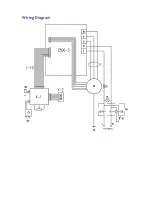
Страница 47: ...Wiring Diagram ...

Отзывы: