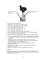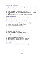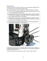
For normal turning, use the following gears.
A B C D
20 80 20 80
The change gears are commonly tight on the shaft when new. You might need
to use a screwdriver behind them to pry them off.
Gear positions B and C are on a hollow shaft that comes off easily when the
retaining socket head cap screw is removed. Then you can use an arbor press to
remove the gears from the hollow shaft. Be careful that you do not lose the
key.
Gear position D has a spacer behind the gear. When you only use three gears,
put the spacer on outside the gear so the gear will align with the gear in
position B.
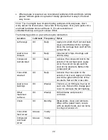
In the change gear chart, many of the combinations have “Any” in column B.
This means that you can use a gear with any number of teeth in position B. It is
an idler and does not affect the overall gear ratio. Use a gear that makes it
easy to properly engage the gears. For these combinations, you can use any
gear for position C; this gear acts only as a spacer and does not engage the
other gears.
To change the gears:
1.
Using a 4 mm hex wrench, remove the change gear cover.
2.
Using 4 mm and 5 mm hex wrenches, remove all three retaining socket head
cap screws from the ends of the shafts.
3.
Use a 10 mm end wrench to loosen the nut that is on the back end of the
shaft in position B-C. This allows the B-C shaft to move in the adjustment
slot.
4.
Use a 14 mm end wrench to loosen the nut on the arc below and behind the
gear in position D. This allows the entire bracket on which the B-C shaft
mounts to swing down.
5.
Remove all the gears.
6.
If you will be using three gears, remove the spacer behind the D position
gear from the end of the lead screw. Be careful that you do not lose the
key.
7.
Replace the gears with the gears shown in the chart for the threads per inch
that you want to cut.
8.
If you will be using three gears, replace the spacer outside the D position
gear on the end of the lead screw. Be sure to insert the key.
9.
If you are using three gears, place any gear in position C to act as a spacer.
10.
Replace the three retaining socket head cap screws from the ends of the
shafts. Snug, but do not tighten, until the gear train is adjusted.
11.
Move the B-C shaft until all the gears are properly engaged.
Содержание HiTorque 5100
Страница 42: ...42 Parts Diagram ...
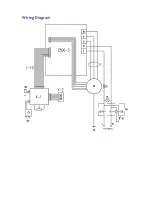
Страница 47: ...Wiring Diagram ...

