page 3
INSTALLATION INSTRUCTIONS
1. PREPARE FOR INSTALLATION
Remove fixture components and parts pack.
Check to ensure
all parts are included.
Note:
Account for small parts and destroy
packing material, as these may be hazardous to children.
2. SELECT MOUNTING LOCATION
D
G
A
B
C
E
H
F
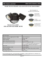
FIXTURE PACKING LIST
Part Description
Quantity
A Light Fixture..........................................................................
1
B
Lamp Head
...........................................................................
2
C Accent Light / Motion sensor ................................................
1
D Mounting bracket (pre-installed)
..........................................
1
E 2” #8 Center Mounting Screw (pre-installed) .......................
1
F 3/4” #8 & #6 & #10 Mounting Screws* ................................ 6
G Wire Nuts* ............................................................................
3
H Rubber Plug*........................................................................
1
*Contained in parts packs
Mounting Hardware Included
Silicone Sealant Required
REQUIRED TOOLS
For installation to properly installed and grounded UL listed round
recessed or surface mounted weatherproof junction box.
Suitable for wall mount
between 6 to 8ft (1,8-2,4m) height with
Accent light facing the ground. Not suitable for mounting within 4
ft
(1.2m) from ground
Note:
Mounting fixture above or below the recommended height
may cause motion sensor not to work properly. If fixture is mounted
higher than 8ft (2.4m), the distance
and downward sensitivity
will be reduced. The detector is less sensitive to motion directly
towards it.
Do
NOT
use with dimmers or timers or on multiple switch circuits.
Do
NOT
install on the same circuit with an electric motor (i.e.
appliances, HVAC equipment, washer/dryer, garage door
openers, etc.
Do
NOT
install near objects that change temperature rapidly, such
as heating vents and air conditioners. These heat sources
could cause false triggering.
Do
NOT
install Nearby large, light-colored objects reflecting light
may trigger the shut-off feature. Do not point other lights at the
daylight sensor.
Turn OFF Power at circuit breaker box
CAUTION:
Do not rely on wall switch alone to turn off power.
3. INSTALLING MOUNTING BRACKET
Note:
Center mounting screw and bracket are pre-installed on the
light fixture for shipping.
•
Loosen the center mounting screw (E) and remove the
mounting bracket.
•
Install the mounting bracket
(D) to the junction box using two
3/4” #6 or #8 or #10 mounting screws (F).
Note:
Choose one of the 3 screw sizes provided depending on
your junction box.
6. FIXTURE INSTALLATION
•
Align fixture over j-box and secure to mounting bracket by
tightening center mounting screw (E).
Note:
Make sure no wires are pinched before tightening.
•
Insert rubber plug (H) into center hole to cover the center
mounting screw head for moisture seal.
4. CAUTION: WIRING
Make sure power is turned off.
•
Use wire nut to connect the bare copper or green house
supply ground wire to the green fixture ground wire.
Note:
If house wiring does not include a ground wire, consult your
local electrical code for approved grounding methods.
For proper connection, place wire nut over wires
and twist clockwise until tight.
•
Use wire nut to connect the white fixture wire to the white
(neutral) house supply wire.
•
Use wire nut to connect the black fixture wire to the black
house supply wire.
5. MOISTURE SEAL
•
Apply silicone caulking (not included) around perimeter of the
fixture where it contacts the mounting surface
to avoid water
entry.
Turn on electricity at fuse or circuit breaker box and make sure the
wall switch is on.
Note: Light will not come on during daylight.
•
Cover Light Sensor to verify success of installation.
NLightend
UNLESS OTHERWISE SPECIFIED
ALL DIMENSIONS ARE IN MILLIMETERS
100MM OR MORE ± 0.5
0 TO 99MM ±
0.10
ANGULAR TOL ±
1/2 ° .
DO NOT SCALE DRAWING
B
SHT I
DRAWN BY: DRS
CHECKED BY:
REV. DESCRIPTION
DRAWN/CHECK
DATE
CONFIDENTIAL: NLightend Proprietary Use Only
2.000
SCALE


