


ALPHA series engines worksHoP mAnuAL
20
7. Torque the nut to 34.0Nm (25.0lbf ft).
8. Replace the fuel pipes.
9. To ensure the control lever is positively stopped by
the control lever stop screw and not the fuel pump
stops refer to "2.55 Setting the Stop/Run Lever".
2.13.4 fuel Pump shims
The shims fitted by the pump manufacturer between
the pump flange and the steel plate must not be
removed or added to.
2.13.5 fuel Pump shim Packs
Extreme care must be taken to ensure that the
individual shim packs that are fitted between each
fuel pump plate and the crankcase are retained with
their original respective cylinder.
The colour coded shims are available in three
sizes:
Green
0.075mm (0.003in).
Slate blue or white 0.125mm (0.005in).
Black
0.250mm (0.010in).
2.14 fueL PumP timing
It will only be necessary to carry out pump timing
if the original shims have been lost or mixed with
those of another pump.
The following shim combinations are used to vary
the timing.
Change
Shim Combination
1º
1 Green
2º
1 Green and 1 slate blue or white
3º
1 Green and 1 black
4º
2 Green and 1 black
To advance the timing - remove shims.
To retard the timing - add shims.
2.14.1 Piston displacement method
The following sequence of operations must be
repeated for each pump as necessary, using the
appropriate firing degree mark on the flywheel.
1. Rotate the piston to TDC on the firing stroke.
2. Use a suitable probe resting on top of the piston, on
the gudgeon pin axis, to accurately determine TDC.
3. Rotate the flywheel clockwise to beyond the
specified piston displacement, as given in "2.15
Fuel Pump Timing Values", from TDC.
The correct figure for the type and build of engine
must be used.
4. Carefully rotate the flywheel anti clockwise until
the correct piston displacement figure is reached.
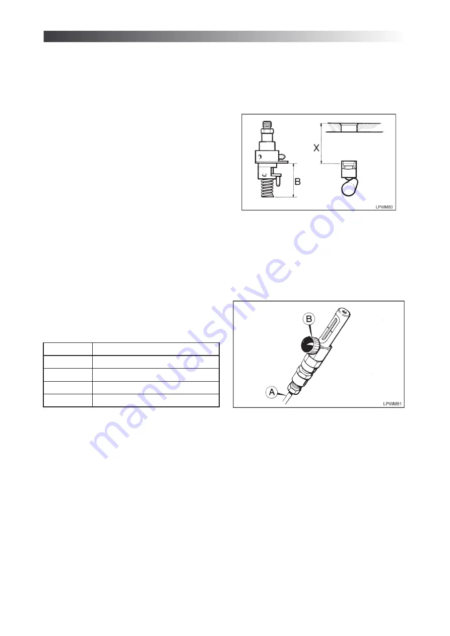
5. Use a probe to measure dimension ‘X’ which is
from the top face of the crankcase, to the top of
the fuel pump tappet cap.
6. Subtract dimension ‘X’ from dimension ‘B’ to give
the required thickness of shim pack to be fitted
between the fuel pump plate and the crankcase.
Figure 2.14.1 Fuel Pump Timing Dimension
B = 51.2mm (2.012in) at port closure
2.14.2 timing gauge method
1. Assemble the pipe (A) to the gauge ensuring that
the pipe nuts are tight.
2. Remove the fuel pipe from the pump to the injector.
3. Connect the gauge and pipe to the fuel pump
delivery union for the cylinder being time.
Figure 2.14.2 Fuel Pump Timing Gauge - 317-50518 -
Lister Petter Service Tool
4. Bleed the fuel filter and pump.
5. Ensure the fuel pump rack is in the run position.
6. Turn the flywheel in the direction of rotation to
prime the gauge.
7. Turn the flywheel until the relevant timing figure
is visible on the compression stroke.
8. Turn the flywheel against rotation for 50mm (2.0in).
9. Slowly release the gauge knob (B) until the fuel
level is in line with the calibration mark on the
gauge sight glass.
10. Turn the engine in the direction of rotation
extremely slowly, until the fuel in the sight glass
just moves.
11. Check that the correct flywheel timing figure, as
given in "2.15 Fuel Pump Timing Values", is visible.
12. Remove the gauge and replace the pump to
injector pipe.
Содержание 0600123LPW3A01
Страница 1: ...LPW LPWS TURBO ENGINES WORKSHOP MANUAL ALPHA SERIES P027 08240 ...
Страница 87: ...87 ...