background image

6

lippert.com 

    432-LIPPERT (432-547-7378)   


Rev:06.30.22

JT’s Strong Arm


Travel Trailer

Installation and Owner’s Manual

(For Aftermarket Applications)

CCD-002345

Fig.7 

10. 

Tighten “T”-bolts until snug. To ensure proper 

installation, make sure the warning labels are facing 

outward and right-side up. The T-bolts should also be on 

the top side of the stabilizers.  

11. 

Repeat Steps 9 and 10 for opposite side.

12. 

Fully retract the front scissor jacks. 

13. 

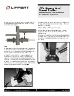
Attach the clevis end of the stabilizer inner tube to the 

swing-bolt tab on the front side of the jack using a 


3/8

” - 16 x 1 ½” bolt with a 

3/8

” washer on the top and bottom 

of the tab and a 

3/8

” locking nut 

(Fig.6)

. Tighten nut until 

tight.  Repeat this step on the opposite side.

14. 

Insert a 

3/8

” x 1 ¼” swing-bolt into a spacer mount and 

secure with a 

3/8

” washer and 

3/8

” locking nut.

15. 

Attach assembled spacer mount to clevis end of 


the stabilizer outer tube using a 

3/8

” - 16 x 1 ½” bolt and 


3/8

” washer on both sides of the clevis Tighten 


3/8

” locking nut enough to allow the stabilizer to swivel 

by hand with some resistance.  Repeat this step for the 

opposite side 

(Fig. 7)

16. 

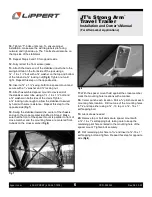
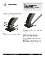
Swing the stabilizer toward the center of the chassis 

and up to the cross-member identified in Step 2. Make 

sure that the front of the spacer mount is parallel to front of 

cross-member and the mounting holes are centered front-

to-back on the cross-member 

(Fig.8)

.

17. 

With the spacer mount held against the cross-member, 

mark the mounting hole locations with a marker.

18. 

Center punch each location. Drill a 

1/8

” pilot hole at each 

mounting hole location.  Drill out one of the mounting holes 

to 

5/16

”and tap either using a 

3/8

” - 16 tap or a 

3/8

” - 16 x 1” 

self-tapping bolt.

19. 

Lubricate as needed.

20. 

Remove tap or bolt and secure spacer mount with 

3/8

”- 16 x 1” self-tapping bolt, taking care to keep the 

remaining pilot hole centered in the mounting hole of the 

spacer mount. Tighten bolt securely. 

21. 

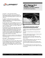
Drill remaining pilot hole to 

5/16

” and insert a 

3/8

”-16 x 1” 

self-tapping bolt and tighten.  Repeat this step for opposite 

side 

(Fig.8)

.

Fig.8 

Содержание 191025

Страница 1: ...tions I or H Beam 7 Operation 10 Scissor Jack Extend 10 Scissor Jack Retract 10 JT s Strong ArmTM Travel Trailer Installation and Owner s Manual For Aftermarket Applications JT s Strong Arm Travel Tra...

Страница 2: ...ERSONAL INJURY OR SEVERE PRODUCT OR PROPERTY DAMAGE NEVER LIFT THE UNIT COMPLETELY OFF THE GROUND LIFTING THE UNIT SO THE WHEELS ARE NOT TOUCHING THE GROUND WILL CREATE AN UNSTABLE AND UNSAFE CONDITIO...

Страница 3: ...044 Nut 16 Nylon Insert Lock Nut 30 E 135840 Flat Washer 48 F 155004 Bolt 16 x 1 Hex Cap Screw 18 G 191010 Bolt 16 x 1 Swing Bolt 6 H 191011 Bolt 16 x 4 Swing Bolt 6 I 191013 Stiffening Pad 2 3 4 x 1...

Страница 4: ...ectric stabilizer jacks Fig 2 refer to the Installation for Electric Stabilizer Jacks section Fig 2 Rear electric stabilizer jack Fig 1 Scissor jack Tape measure Felt tip black marker Hammer Center pu...

Страница 5: ...h so that the swing bolt will only pivot by using a screwdriver for leverage Ensure swing bolt tab is positioned horizontally 5 Remove the existing lower outside pivot bolt replacing with 4 swing bolt...

Страница 6: ...d a 3 8 washer on both sides of the clevis Tighten a 3 8 locking nut enough to allow the stabilizer to swivel by hand with some resistance Repeat this step for the opposite side Fig 7 16 Swing the sta...

Страница 7: ...bolt 3 8 washer and 3 8 locking nut Repeat this step for opposite side Fig 9 I or H beam main rails or tubular frames and or insulated 1 Measure from the rear side of the front scissor jack 27 and pla...

Страница 8: ...ke sure the swing bolt tab is positioned horizontally NOTE If scissor jacks are less than 2 wide washers will be necessary on the swing bolt because the threads may not be long enough 14 Prepare T bol...

Страница 9: ...of the rear cross member 3 Center punch and drill an 3 8 pilot hole at each mounting hole location 4 Drill out the hole closest to the rear jacks to 5 16 and tap using either a 3 8 16 tap or 3 8 16 x...

Страница 10: ...our front Strong Arm Jack Stabilizers Electric Stabilizer Jack Extend 1 Level your trailer side to side 2 Lower the front of the trailer 3 4 lower than the rear 3 Lower and set rear jacks evenly 4 Tig...

Страница 11: ...bilizers 7 Briefly press the electric jack switch so the jacks slightly lift the front of the trailer This eliminates the play movement at the bolts and bolt holes between the stabilizers and the trai...

Страница 12: ...ates Fig 14A to holes in foot pad Place the smaller half down and on the outside of footpad brackets Fig 14B Fig 14 Fig 15 Fig 13 3 Loosely install 3 8 16 x 4 swing bolt Fig 15A two 3 8 SAE flat washe...

Страница 13: ...ig 16 6 Attach JT Strong Arm Stabilizer Fig 17A to the swing bolt 7 Align stabilizer mounting holes over the swing bolt mounting hole 8 If necessary use screwdriver to adjust orientation of swing bolt...

Страница 14: ...uid Each footpad requires a different number of lugs Installation 1 Measure 1 1 4 from the edge of the footpad inward and onto one of the star points on top of the footpad The front face of the lug wi...

Страница 15: ...6 30 22 JT s Strong Arm Travel Trailer Installation and Owner s Manual For Aftermarket Applications CCD 002345 Notes Maintenance Using a clean and dry cloth periodically wipe the Strong Arms with wate...

Страница 16: ...as a complete document only unless Lippert provides explicit consent to distribute individual parts All manual information is subject to change without notice Revised editions will be available for fr...

Отзывы: